AI technical title is built by PatSnap AI team. It summarizes the technical point description of the patent document.
a wellbore and system technology, applied in the field of wellbore, can solve the problems of destabilizing the formation, generating disposal problems, and often undesirable fracturing using aqueous fluids, and achieve the effect of superior line canceling harmonics
Inactive Publication Date: 2015-04-30
PROSTIM LABS
View PDF12 Cites 218 Cited by
Summary
Abstract
Description
Claims
Application Information
AI Technical Summary
This helps you quickly interpret patents by identifying the three key elements:
Problems solved by technology
Method used
Benefits of technology
Benefits of technology
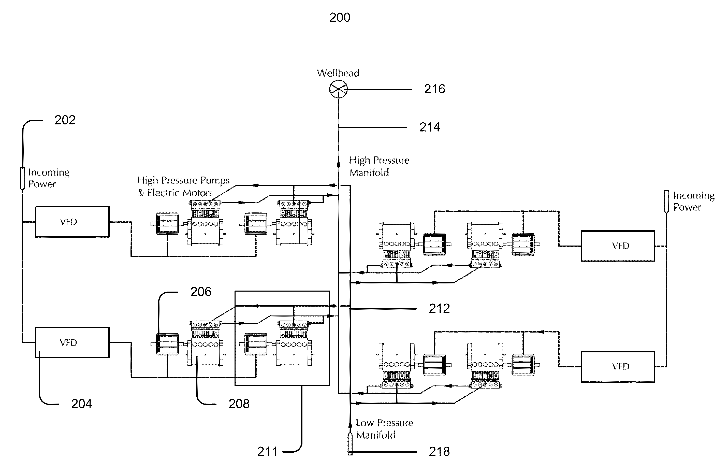
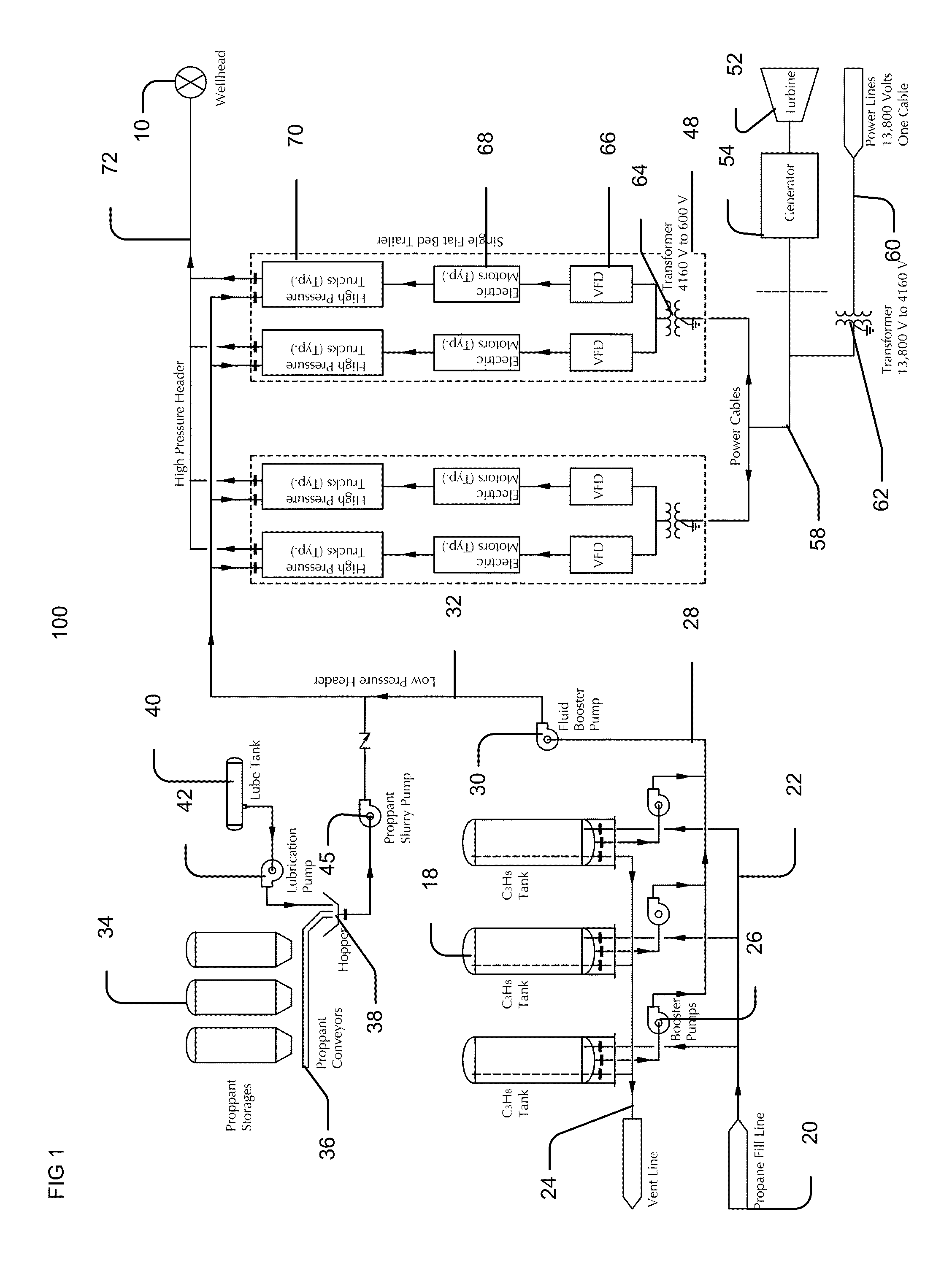
The patent describes a system for powering equipment on a mobile vehicle at a worksite using a single electric conduit. This eliminates the need for multiple cabling and conduits. The system also includes a transformer and a VFD (voltage-fed driver) that can be positioned at different locations on the vehicle. One advantage of this configuration is that it prevents potential danger from ignition sources (the VFD) near the fracturing materials, which may be volatile.
Problems solved by technology
Fracturing using aqueous fluids is often undesirable due to the negative effects of water on the formation.
For example, clays and other formation components can swell when exposed to water, while salts and other formation components may dissolve, such that exposure to a significant quantity of water can destabilize a formation.
Use of water and other aqueous fluids also generates issues regarding disposal.
Such a process can add considerable time and expense to a fracturing operation.
Additionally, many hydrocarbon-based fluids are volatile and / or otherwise unsuitable for use at wellbore temperatures and pressures, while lacking the density sufficient to carry many types of proppant.
Use of chemical additives generates waste and disposal issues similar to those encountered when performing fracturing operations using aqueous fluids.
Conventionally, such equipment is driven / powered using diesel engines, which can be responsible for significant quantities of noise, pollution, and expense at a worksite.
Electric drive systems have been contemplated as an alternative to diesel engines; however, such systems require numerous pieces of equipment, extensive cabling and / or similar conduits, and typically utilize on-site power generation, such as a natural gasturbine.
Use of turbine prime movers and similar equipment may be unsuitable when utilizing fracturing fluids that include flammable components.
Method used
Image
Click on the blue label to locate the original text in one second.
Reading with bidirectional positioning of images and text.
Examples
Embodiment Construction
[0045]Reference now should be made to the drawings, in which the same reference numbers are used throughout the different figures to designate the same components.
[0046]Before describing selected embodiments of the present invention in detail, it is to be understood that the present invention is not limited to the particular embodiments described herein. The disclosure and description herein is illustrative and explanatory of one or more presently preferred embodiments of the invention and variations thereof, and it will be appreciated by those skilled in the art that various changes in the design, organization, order of operation, means of operation, equipment structures and location, methodology, and use of mechanical equivalents may be made without departing from the spirit of the invention.
[0047]As well, it should be understood the drawings are intended illustrate and plainly disclose presently preferred embodiments of the invention to one of skill in the art, but are not intend...
PUM
Abstract
The disclosure contained herein describes systems, units, and methods usable to stimulate a formation including a pump usable to pressurize fluid, an electric-powered driver in communication with and actuating the pump, and an electrical power source in communication with and powering the electric-powered driver. The electrical power source can include on-site generators and / or grid power sources, and transformers can be used to alter the voltage received to a voltage suitable for powering the electric-powered driver. Air moving devices associated with the electric-powered driver can be used to provide air proximate to the pump to disperse gasses. In combination with fluid supply and / or proppant addition subsystems, the pump can be used to fracture a formation.
Description
CROSS-REFERENCE TO RELATED APPLICATIONS[0001]This applications claims priority to U.S. Provisional Application for patent, having the Application Ser. No. 61 / 889,187, filed Oct. 10, 2013.[0002]This application further claims priority to U.S. Non-Provisional application for patent, having the application Ser. No. 14 / 99461, and further claims priority to claims priority to the U.S. Provisional Application for patent, having the Application Ser. No. 61 / 774,237, filed Mar. 7, 2013; the U.S. Provisional Application for patent, having the Application Ser. No. 61 / 790,942, filed Mar. 15, 2013; the U.S. Provisional Application for patent, having the Application Ser. No. 61 / 807,699, filed Apr. 2, 2013; the U.S. Provisional Application for patent, having the Application Ser. No. 61 / 870,350, filed Aug. 27, 2013; the U.S. Provisional Application for patent, having the Application Ser. No. 61 / 889,187 filed Oct. 10, 2013; and the U.S. Provisional Application for patent, having the Application Ser....
Claims
Application Information
Patent Timeline
Application Date:The date an application was filed.
Publication Date:The date a patent or application was officially published.
First Publication Date:The earliest publication date of a patent with the same application number.
Issue Date:Publication date of the patent grant document.
PCT Entry Date:The Entry date of PCT National Phase.
Estimated Expiry Date:The statutory expiry date of a patent right according to the Patent Law, and it is the longest term of protection that the patent right can achieve without the termination of the patent right due to other reasons(Term extension factor has been taken into account ).
Invalid Date:Actual expiry date is based on effective date or publication date of legal transaction data of invalid patent.
IPC IPC(8): E21B43/26E21B43/267
CPCE21B43/267E21B43/26C09K8/62E21B43/2607
InventorLESTZ, ROBERT S.THRASH, JOHN F.BYRD, AUDIS C.JUNKINS, JAMES H.MYERS, NORMAN S.CARROLL, DAVID A.

