Antenna device and electric appliance using the same

Inactive Publication Date: 2005-04-12
TDK CORPARATION
View PDF14 Cites 114 Cited by
  • Summary
  • Abstract
  • Description
  • Claims
  • Application Information

AI Technical Summary

Benefits of technology

In a preferred embodiment of the invention, the opening is closed by an insulating member. As a result, the antenna element incorporated in th

Problems solved by technology

In the prior art, however, the incorporated antenna element is unidirectional, and com

Method used


Image

  • Antenna device and electric appliance using the same
  • Antenna device and electric appliance using the same
  • Antenna device and electric appliance using the same

Examples


Embodiment Construction

Preferred embodiments of the invention are specifically described below by referring to the drawings. In the accompanying drawings, same reference numerals are given to same members, and duplicate explanation is omitted. The embodiments of the invention are particularly useful examples, and the invention is not limited to the illustrated embodiments alone.

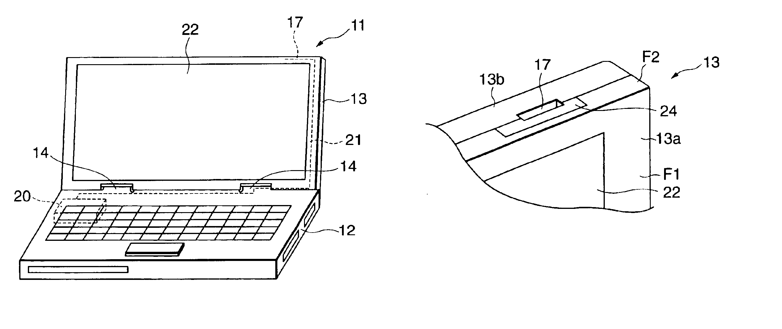
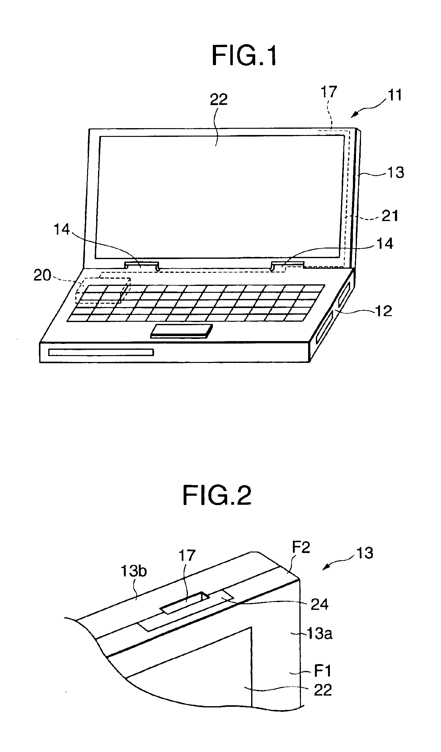
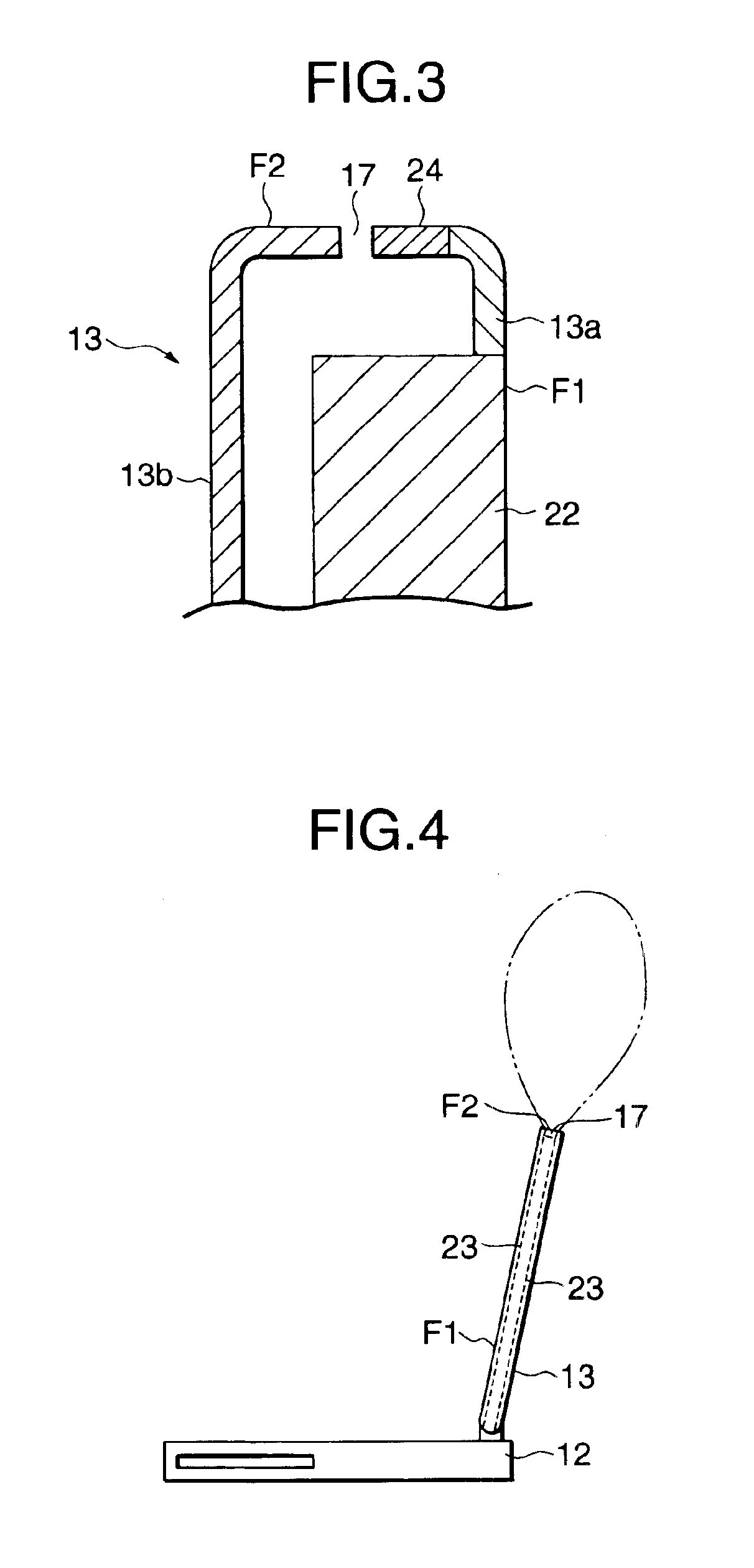
FIG. 1 is a perspective view showing a personal computer using an antenna device in an embodiment of the invention, FIG. 2 is a perspective view showing essential parts of the antenna device disposed in the personal computer in FIG. 1, FIG. 3 is a sectional view of FIG. 2, FIG. 4 is an explanatory diagram showing radiation direction of a radio wave by an antenna element disposed in the personal computer in FIG. 1, FIG. 5 is a perspective view showing essential parts of an antenna device in other embodiment of the invention, FIG. 6 is a sectional view of FIG. 5, FIG. 7 is a perspective view showing essential parts of an antenna devi...


PUM


Abstract

In an antenna device, an antenna element incorporated in a housing provided with a display unit is omnidirectional. An antenna device comprises a housing for allowing a display unit for displaying visual information to be disposed on the principal surface F1, and an antenna element incorporated in the housing for radiating a radio wave from an end face F2 contacting with the principal surface F1 of the housing.

Description

BACKGROUND OF THE INVENTIONThe present invention relates to an antenna device and an electric appliance using the same.Today, electric appliances such as personal computers are mostly provided with communication functions for connecting to commercial networks or building up a LAN. As communication formats, needs for wireless communications are rapidly increasing owing to various conveniences because cables are not needed unlike wired communications.An example of an antenna device incorporated in a conventional personal computer is shown in FIG. 27.In FIG. 27, a personal computer 111 comprises a main body side housing 112 accommodating a keyboard and various electric components, and a display side housing 113 including a display unit 122 for displaying visual information by electric means.An antenna element 117 is built in a side part of the display side housing 113, and electric power of specified frequency is supplied from a current feeding unit 120 provided in the main body side h...

Claims


Application Information

Patent Timeline
IPC IPC(8): G06F1/16H01Q1/22H01Q9/04H01Q13/10
CPCG06F1/1616H01Q1/22H01Q13/10H01Q9/0407H01Q1/2266H01Q5/378H01Q13/16
Inventor SATO, MASAHIDE
Owner TDK CORPARATION
Why Eureka
Try Eureka