Back light unit in liquid crystal display

a back light unit and liquid crystal display technology, applied in the field of liquid crystal display, can solve the problems of increasing the loss of light being transmitted to the liquid crystal panel, increasing manufacturing costs, etc., and achieve the effect of reducing the brightness of the light input, reducing the resection of the pattern and the wall surfa

Inactive Publication Date: 2005-04-12
LG DISPLAY CO LTD
View PDF11 Cites 18 Cited by
  • Summary
  • Abstract
  • Description
  • Claims
  • Application Information

AI Technical Summary

Benefits of technology

Accordingly, it is an object of the present invention to provide a back light unit in a liquid crystal display that mini

Problems solved by technology

The extra prism and the diffusion sheets absorb more light and thus cause an increased loss

Method used


Image

  • Back light unit in liquid crystal display
  • Back light unit in liquid crystal display
  • Back light unit in liquid crystal display

Examples


Embodiment Construction

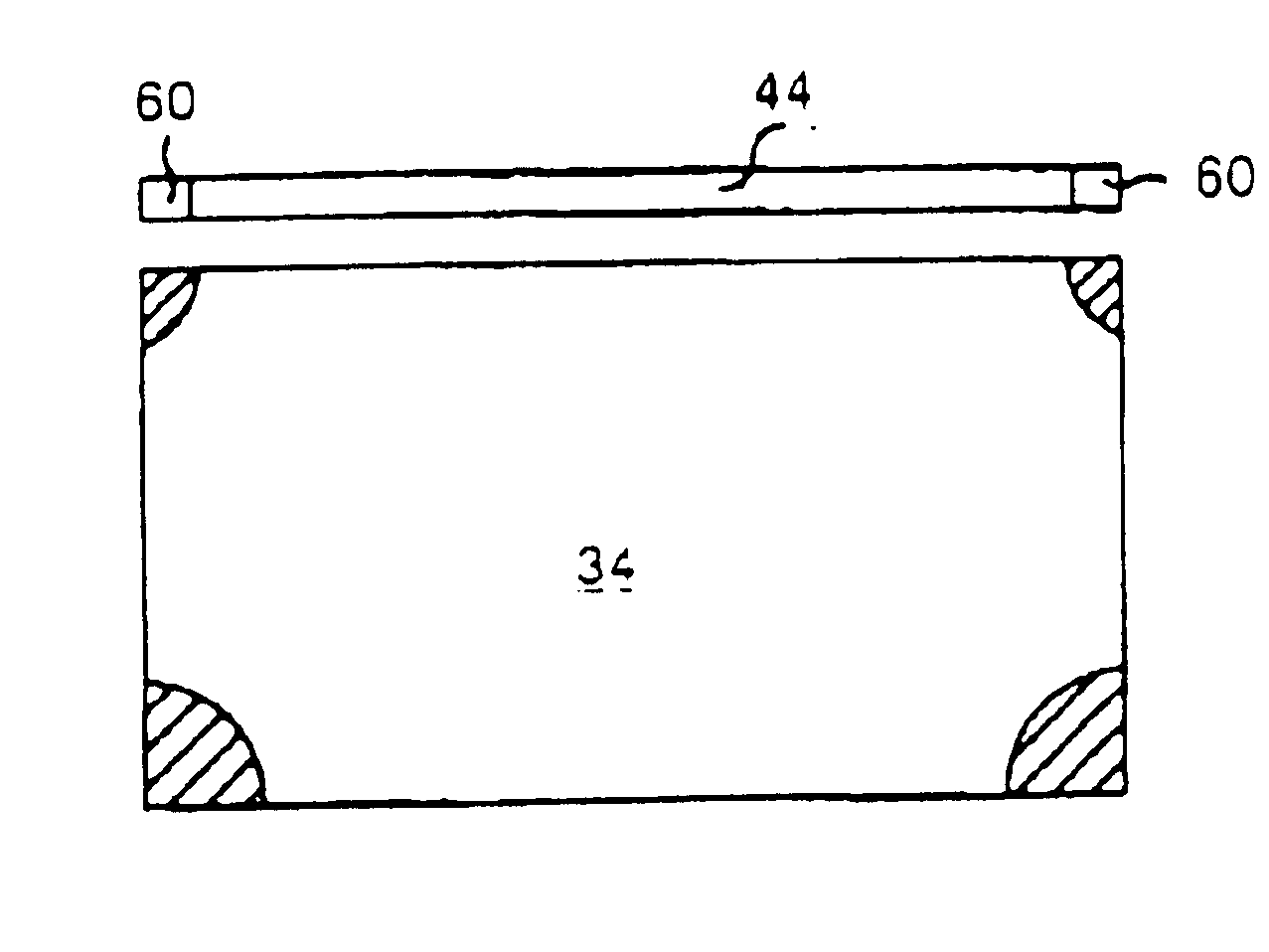
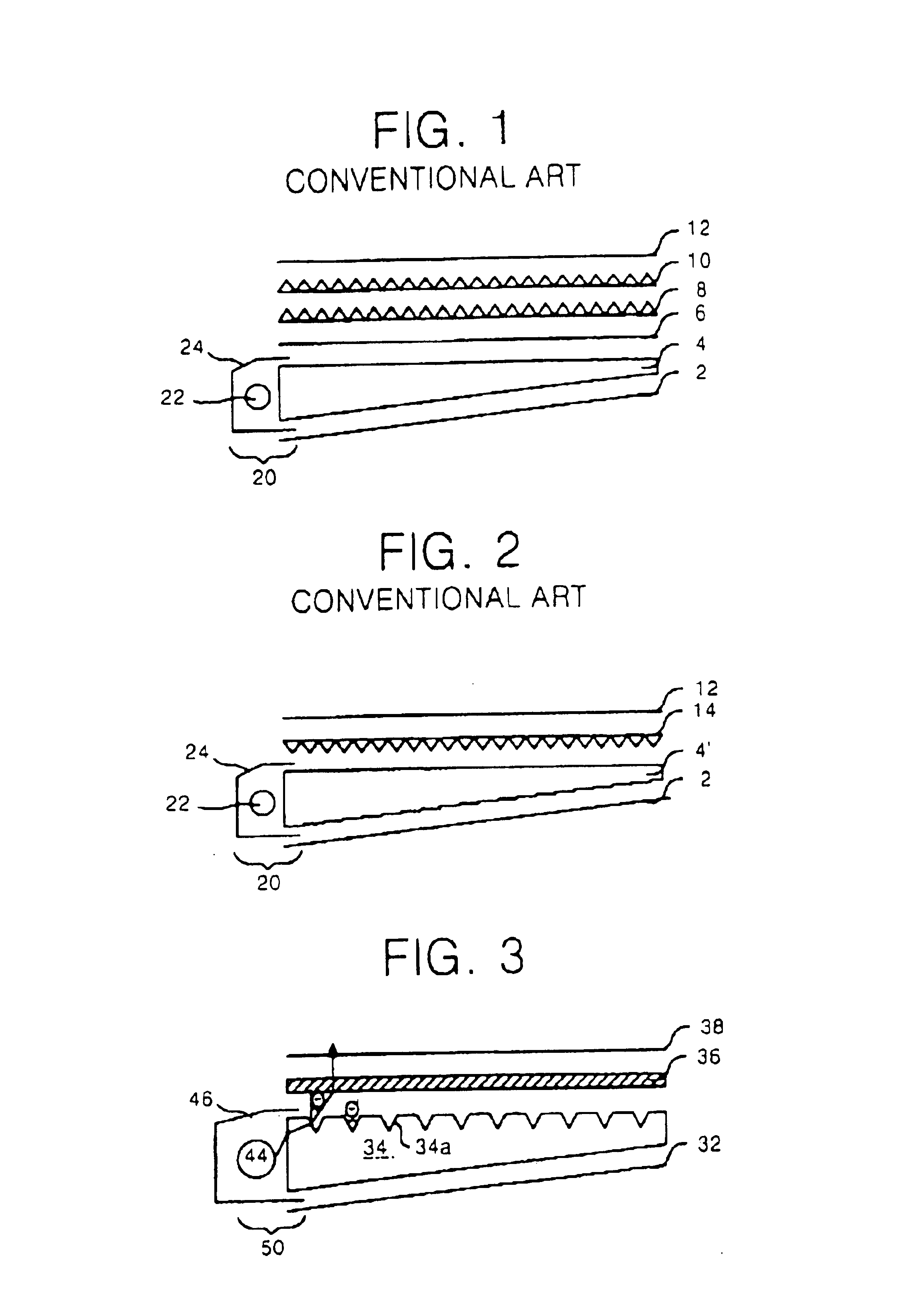
A back light unit according to an embodiment of the present invention is shown in FIG. 3. The back light unit includes a light-guide plate 34 including a cone pattern 34a. The cone pattern 34a uniformly distributes light from a light input 50. The cone pattern 34a can be distributed either on an upper surface or a lower surface of the light-guide plate 34.

A reflective plate 32, disposed under the light-guide plate 34, reflects light from the light input 50 in an upward direction. A light-path converter 36 controls the light such that it enters perpendicularly to a surface of a liquid crystal display panel (not shown). Finally, a diffusion sheet 38 diffuses the light passing through the light-path converter 36.

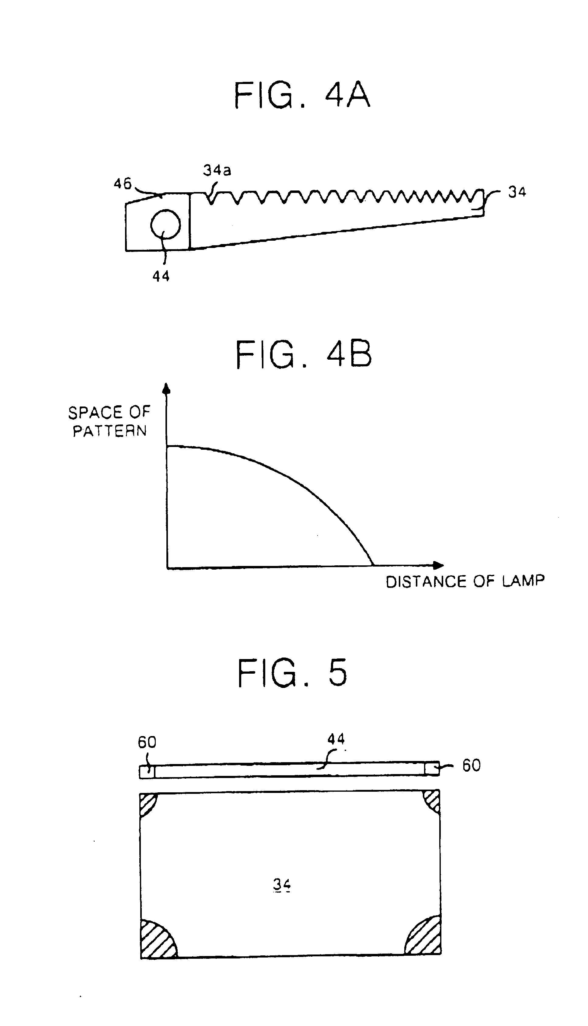
FIGS. 4A and 4B explain the relationship of the density of cones in the cone pattern 34a to a distribution of light. On the light-guide plate 34, as the distance from the light source increases, the density of the concs of the cone pattern 34a increases. Stated another way, spa...


PUM


Abstract

In a black light unit, a light-guide plate is provided with a cone pattern to uniformly guide a light beam passing through a light input. A light-path converter controls a progress direction of the light beam in such a manner that the light beam outputted from the light-guide plate is progressed in a direction perpendicular to a liquid crystal panel. A diffusion sheet diffuses the light beam passing through the light-path converter into the liquid crystal panel. A reflection of the light-guide pattern and wall surface and the bright lines of the light input can be minimized. The light efficiency can be improved and the manufacturing cost can be reduced.

Description

BACKGROUND OF THE INVENTION1. The Field of the InventionThis invention relates to a liquid crystal display, and more particularly to a back light unit in the liquid crystal display that minimizes a reflection of the pattern on a wall surface of a light-guide plate and bright lines from a light input.2. Description of the Related ArtsGenerally, a liquid crystal display (LCD) controls an amount of light transmitted from a back light unit. The transmission is controlled by means of a liquid crystal panel including a number of liquid crystal cells arranged in a matrix and a number of control switches for switching video signals to be applied to the liquid crystal cells, thereby displaying a desired picture on a screen. Conventional back light units will be described with reference to FIG. 1 and FIG. 2.Referring to FIG. 1, the first conventional back light unit includes a light-guide plate 4 for guiding light passing through a light input 20; a reflective plate 2 disposed under the light...

Claims


Application Information

Patent Timeline
IPC IPC(8): G02F1/1335G02F1/13F21V8/00G02B6/00
CPCG02B6/0036G02B6/0061G02B6/0053G02F1/1335
Inventor KIM, JE HONG
Owner LG DISPLAY CO LTD
Why Eureka
Try Eureka