Decoding bit-plane-encoded data using different image quality for display

Inactive Publication Date: 2005-04-12
CANON KK
View PDF11 Cites 59 Cited by
  • Summary
  • Abstract
  • Description
  • Claims
  • Application Information

AI Technical Summary

Benefits of technology

It is a main object of the present invention to provide an image processing technique capable of maintaining th

Problems solved by technology

In storing/transmitting the image, the enormous amount of data poses a problem.
If the band of the network is insufficient, it takes a long time to display the image.
In JPEG, however, the encoding processing is complex, a reduced image or thumbnail image must be generated and encoded, and, for each layer of resolution necessary for decoding, the difference between a result obtained by decoding the reduced image and an image obtained by reducing the ori

Method used


Image

  • Decoding bit-plane-encoded data using different image quality for display
  • Decoding bit-plane-encoded data using different image quality for display
  • Decoding bit-plane-encoded data using different image quality for display

Examples


first embodiment

<First Embodiment>

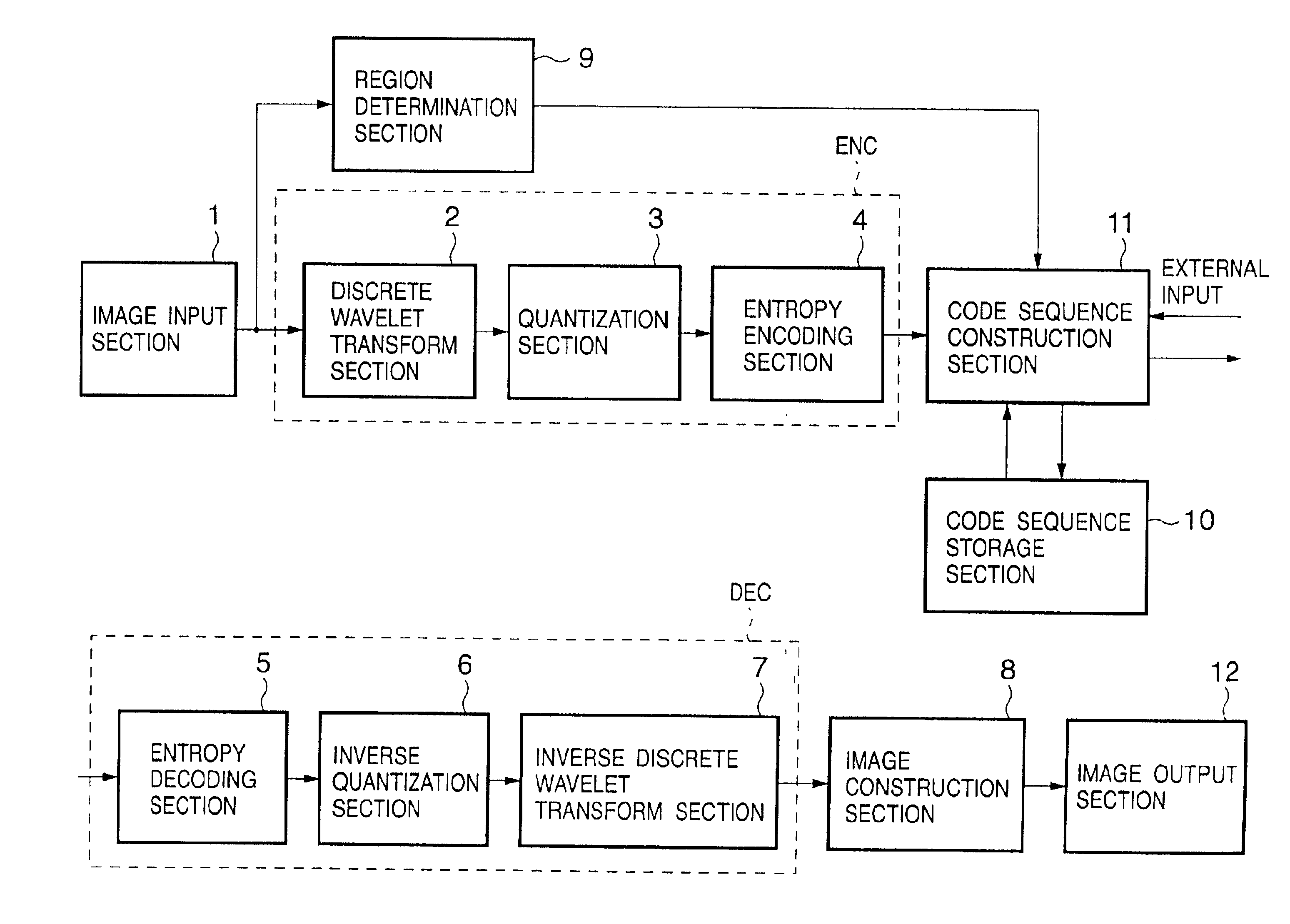
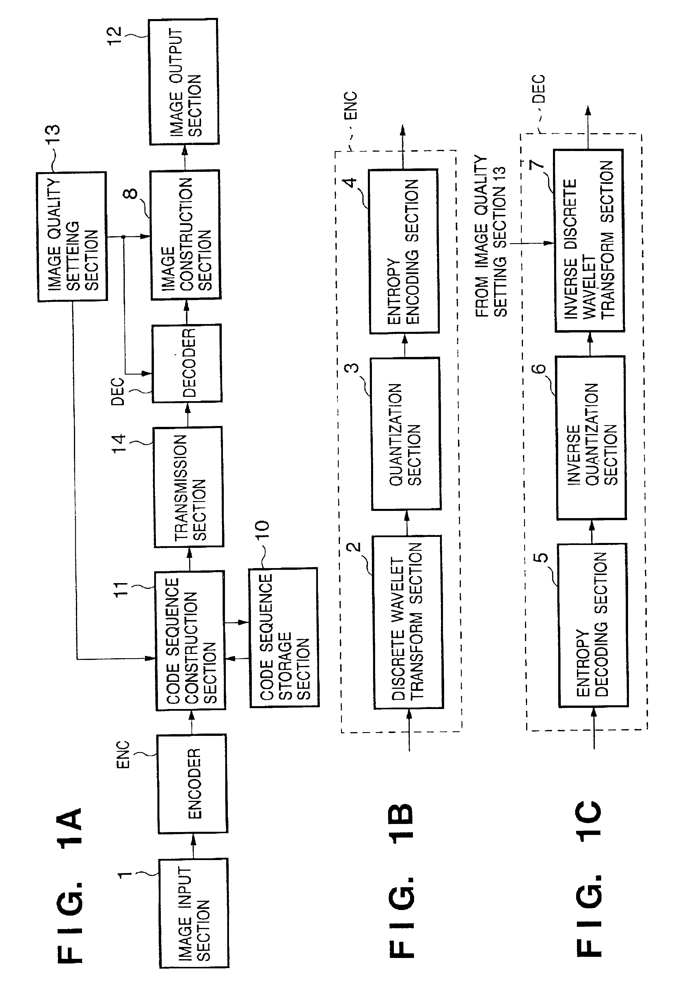
FIGS. 1A to 1C are block diagrams of an image processing apparatus according to an embodiment of the present invention. An outline of operation of the image processing apparatus will be described first with reference to FIGS. 1A to 1C.

Referring to FIGS. 1A to 1C, an image input from an image input section 1 is compression-coded by an image encoder ENC. The generated code sequence is output to a code sequence construction section 11 on the output side. The code sequence construction section 11 constructs the received code sequence by a predetermined method and outputs it to a code sequence storage section 10 or transmission section 14. The code sequence construction section 11 also has a function of changing the structure of a code sequence stored in the code sequence storage section 10 and storing or transmitting the code sequence.

The code sequence storage section 10 is a storage medium such as a memory or hard disk for storing a compression-coded image. The c...

second embodiment

<Second Embodiment>

In the above-described first embodiment, the output code sequence is arranged in units of subbands. However, another arrangement may be employed. A case wherein a code sequence constructed by a code sequence construction section 11 has another form will be described below.

FIGS. 5A to 5E are views showing the structure of a code sequence by the code sequence construction section 11 according to this embodiment. The structures shown in FIGS. 5A to 5C are the same as in the first embodiment, and a detailed description thereof will be omitted. Referring to FIG. 5D, encoded data are put together in units of layers, and each layer contains a predetermined amount of encoded data in each subband.

The encoded data in each subband is formed from encoded data corresponding to a predetermined number of bit planes or encoding paths from the code block in the subband. Operation of each section in outputting an image when such a code sequence is formed will be described belo...

third embodiment

<Third Embodiment>

In the above-described first and second embodiments, the image is not segmented into tiles. However, the present invention is not limited to this, and an image may be segmented into a plurality of tiles. In addition, the output resolution set by the image quality setting section may be changed in units of tiles.

In the third embodiment, an image quality setting section 13 outputs both a display resolution and an output resolution to a code sequence construction section 11. The code sequence construction section 11 stores an image type of each tile in advance by a predetermined method and reconstructs the code sequence such that a code sequence with the output resolution is output for a predetermined tile, and a code sequence with the display resolution is output for the remaining tiles.

FIG. 4C is a view showing an output code sequence when an image is segmented into a plurality of tiles. Referring to FIG. 4C, in tiles 0 and 1, only encoded data of a subband LL ...


PUM


Abstract

An image processing apparatus includes an encoding section and a decoding section. The encoding section includes means for encoding an input image to generate encoded data, means for receiving a designation of an image quality for display of the input image, and means for outputting, of the encoded data, encoded data necessary to display the input image at an image quality equal to or higher than the designated image quality. The decoding section includes means for decoding the encoded data output from the encoding section to generate image data, and means for, when an image based on the image data has an image quality higher than the designated image quality, converting the image data into image data having the designated image quality.

Description

FIELD OF THE INVENTIONThe present invention relates to a field of image processing and, more particularly, to image encoding and decoding.BACKGROUND OF THE INVENTIONAlong with recent remarkable progress in computers and networks, various kinds of information such as character data, image data, and audio data are stored and transmitted in computers or between networks. Of these data, an image and especially a multilevel image contains a very large quantity of information. In storing / transmitting the image, the enormous amount of data poses a problem.Hence, for an application purpose such as an image database which allows image browsing through a network, images in the device for storing them are often compression-coded. To browse these images, all the compression-coded data must be transmitted and decoded. If the band of the network is insufficient, it takes a long time to display the image.In such a case, only part of the compression-coded data is transmitted to display the image at...

Claims


Application Information

Patent Timeline
IPC IPC(8): G06T9/00H03M7/30H03M7/40H04N1/41H04N19/34H04N19/60H04N19/63H04N19/85H04N19/91
CPCH04N19/63H04N19/136H04N19/1883H04N19/17H04N19/162
Inventor SATO, MAKOTOKAJIWARA, HIROSHIKISHI, HIROKI
Owner CANON KK
Why Eureka
Try Eureka