Method and system for automatic bucket loading

a bucket and automatic technology, applied in the direction of thinning machines, process and machine control, instruments, etc., can solve the problems of affecting the efficiency of the work machine, not being able to provide good traction, and not being able to achieve the desired effect of reducing the number of buckets

Inactive Publication Date: 2005-04-12
CATERPILLAR INC
View PDF23 Cites 71 Cited by
  • Summary
  • Abstract
  • Description
  • Claims
  • Application Information

AI Technical Summary

Problems solved by technology

However, as fatigue sets in, or if the operator is relatively inexperienced, the dig cycle may not be as productive as desired.
This adversely impacts the efficiency of the work machine.
For example, the ground may be wet or sandy, and thus not able to provide good traction.
Maintaining the engine at full speed may then cause the work machine to slip excessively as it enters the pile.
This may result in the bucket rising out of the pile without the automated dig cycle loading the bucket to capacity.
However, the known systems, including the system of the '153 patent, do not account for the engine speed at less than the full engine speed or the ground speed at less than the maximum ground speed for a given gear.
Furthermore, the known systems do not address the situation that arises when an operator downshifts when entering a pile, which may change engine speed, and consequently change the lift command.

Method used


Image

  • Method and system for automatic bucket loading
  • Method and system for automatic bucket loading
  • Method and system for automatic bucket loading

Examples


Embodiment Construction

Embodiments of the present invention are now described with reference to the figures where like reference numbers indicate identical or functionally similar elements. Also in the figures, the left most digit of each reference number corresponds to the figure in which the reference number is first used. While specific configurations and arrangements are discussed, it should be understood that this is done for illustrative purposes only. A person skilled in the relevant art will recognize that other configurations and arrangements can be used without departing from the spirit and scope of the invention.

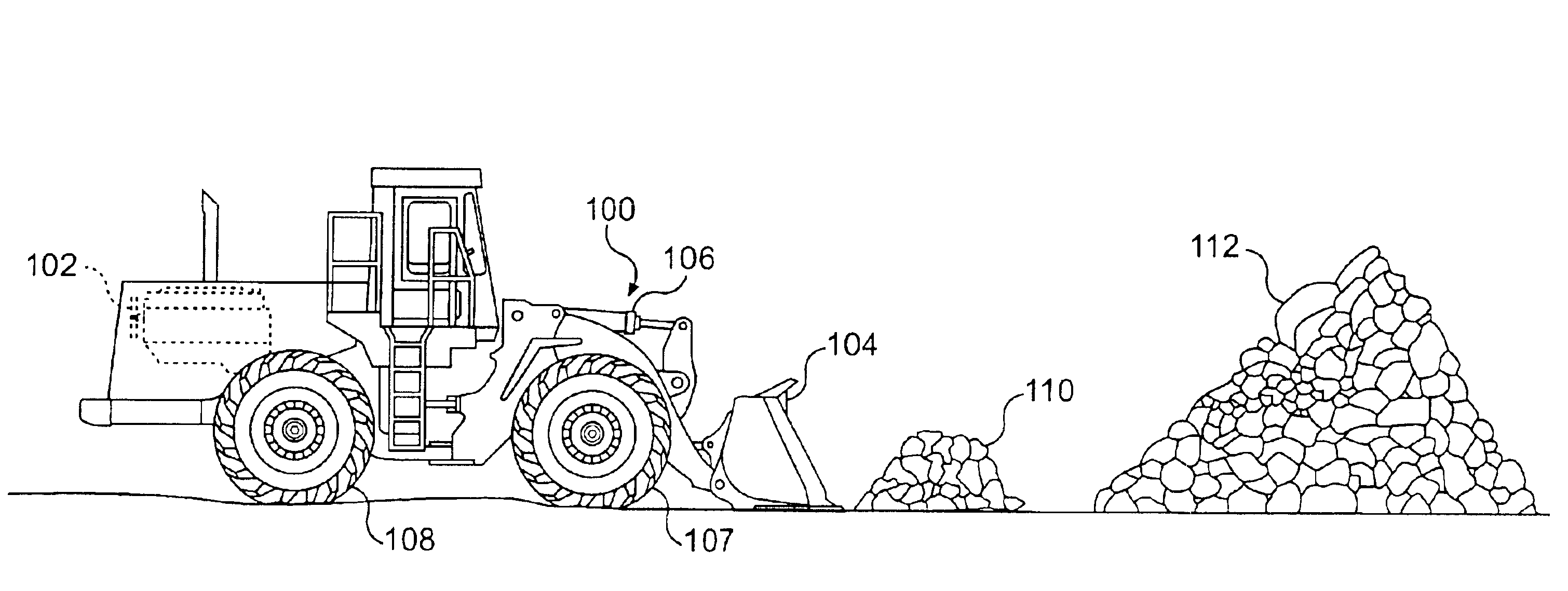
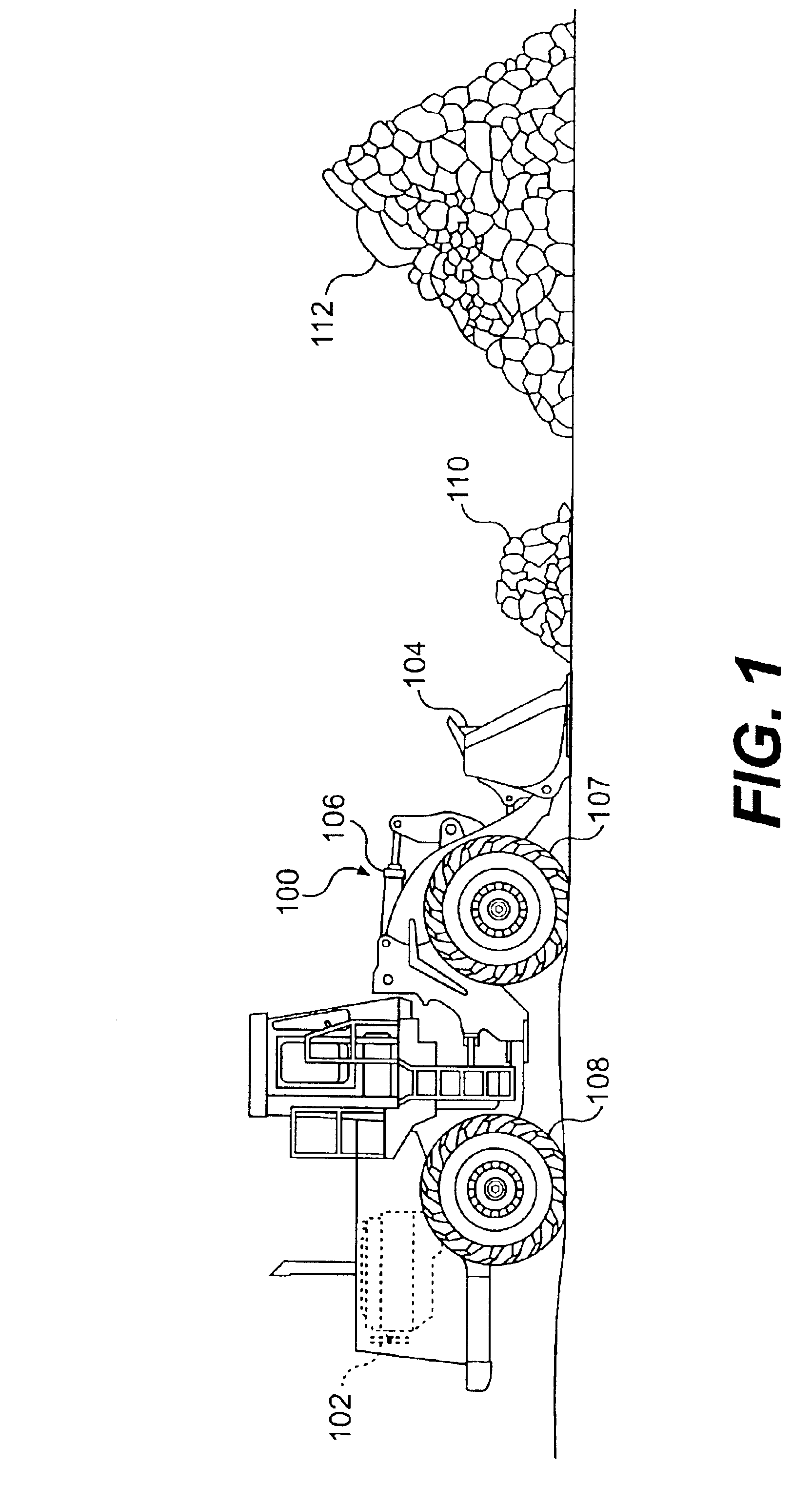
Referring to FIG. 1, a work machine 100 is illustrated approaching a first pile of material 110 and a second pile of material 112. First pile of material 110 and second pile of material 112 may be any of a variety of materials that are to be loaded into the work implement 104 and dumped at another location. For example, first and second piles 110, 112 may include gravel, sand, dirt, and...


PUM


Abstract

A method for controlling an automatic bucket control system during loading of a work implement of a work machine is disclosed. The method includes the steps of determining when the work implement engages a pile of material, initiating the automatic bucket control system in response to the work implement engaging the pile of material, determining a ground speed of the work machine, and generating a lift command based upon the ground speed. After fully engaging the material, the system may further adjust tilt commands and / or lift commands based upon a monitored crowd factor to control operation of the work implement.

Description

TECHNICAL FIELDThis invention relates generally to an automated bucket loading cycle for a digging operation and, more particularly, to a method and system for controlling the automated bucket loading cycle.BACKGROUNDWork machines, for example, wheel loaders, track loaders, and the like, having work implements, such as buckets, are often used to dig material from one location, and dump the material at one or more other locations. For example, wheel loaders having buckets are used to dig materials such as gravel, sand, soil, and the like, and dump the material into the bed of a truck, or at other sites.In a work environment in which the dig and dump process is performed repeatedly for long periods of time, it is desired to work as efficiently and productively as possible. However, as fatigue sets in, or if the operator is relatively inexperienced, the dig cycle may not be as productive as desired. This adversely impacts the efficiency of the work machine.As a result, attempts have be...

Claims


Application Information

Patent Timeline
Patent Type & Authority Patents(United States)
IPC IPC(8): E02F3/43E02F3/42E02F9/20
CPCE02F9/2029E02F3/432
Inventor BUDDE, STEVEN C.
Owner CATERPILLAR INC
Why Eureka
Try Eureka