System, method, and apparatus for attaching a leader pin assembly to data tape on a tape cartridge

a technology of leader pins and data tapes, which is applied in the field of apparatus and methods for attaching or reattaching leader pins to data tapes on tape cartridges, can solve the problems of large amount of cartridge space left unused, large size and shape of leader blocks, and reliability problems in the design of stiff and resilient connection tapes

Inactive Publication Date: 2005-04-19
INT BUSINESS MASCH CORP
View PDF10 Cites 3 Cited by
  • Summary
  • Abstract
  • Description
  • Claims
  • Application Information

AI Technical Summary

Problems solved by technology

For example, if the cartridge is square-shaped, tape wound within the single-spindle cartridge employs significantly more space within the cartridge than tape wound within multiple-spindle cartridges, where a great amount of cartridge space is left unused.
However, since one end of tape within a single-spindle cartridge is commonly removed from the cartridge, drawn into the machine reading from or writing to the tape, and wound around a spindle within the machine, problems arise in the design of an element or assembly which permits the machine to “grab” or “pick” and manipulate the tape end.
A number of designs are well-known in the industry, but each brings with it one or more deficiencies.
A significant disadvantage of the leader block design is its size and shape.
However, the tape splice cartridge design has its own design deficiencies.
For example, reliability problems exist in the design of the stiff and resilient connection tape used to connect the picker to the cartridge tape.
Therefore, a compromise must be made to either stiffen the connection tape (thereby making winding more difficult and increasing the chance of incorrectly-wound tape) to facilitate easier “picking” or relax the connection tape (thereby making the picking procedure more difficult or unreliable).
This compromise can result in a connection or winding which is undesirable.
For example, incorrectly-wound tape may lead to tape damage and / or misfeeding of the tape in the cartridge or machine.
Conversely, when a desired disconnection procedure fails, attempts to release the cartridge from the machine can cause damage to the tape, the cartridge, and / or the machine.
In short, the compromise necessary to provide a connection tape which is both stiff enough to facilitate reliable connections and disconnections while being relaxed enough to be properly wound results in a less-than-optimal design.
The tape splice cartridge design has other undesirable features.
This bump caused by the mylar-to-tape connection is amplified as more tape is wound on the spindle, and has the undesirable effect of creating a “once around” type of runout on the spindle which can distort a recorded signal on the tape.
Another disadvantage of the tape splice cartridge design is the fact that during winding operations, the mylar-to-splice connection passes over the recording head(s) of the machine.
This action exposes the recording heads to potential damage and / or excessive wear.
As described above, although designs exist for connecting the tape of a cartridge to the picker of a machine which reads from and / or writes to the tape, each design suffers from significant drawbacks, including inefficient connection size, connection elements which create difficulty in establishing compatibility between cartridges and machines, and connection elements which are not optimally designed for both winding and connecting operations.
Since there are currently no solutions for reattaching leader pin assemblies to data tape, the cartridge is simply discarded or destroyed.
Although individual ones of the cartridges are relatively inexpensive, simply discarding a cartridge because it no longer has a leader pin can become expensive over time.

Method used


Image

  • System, method, and apparatus for attaching a leader pin assembly to data tape on a tape cartridge
  • System, method, and apparatus for attaching a leader pin assembly to data tape on a tape cartridge
  • System, method, and apparatus for attaching a leader pin assembly to data tape on a tape cartridge

Examples


Embodiment Construction

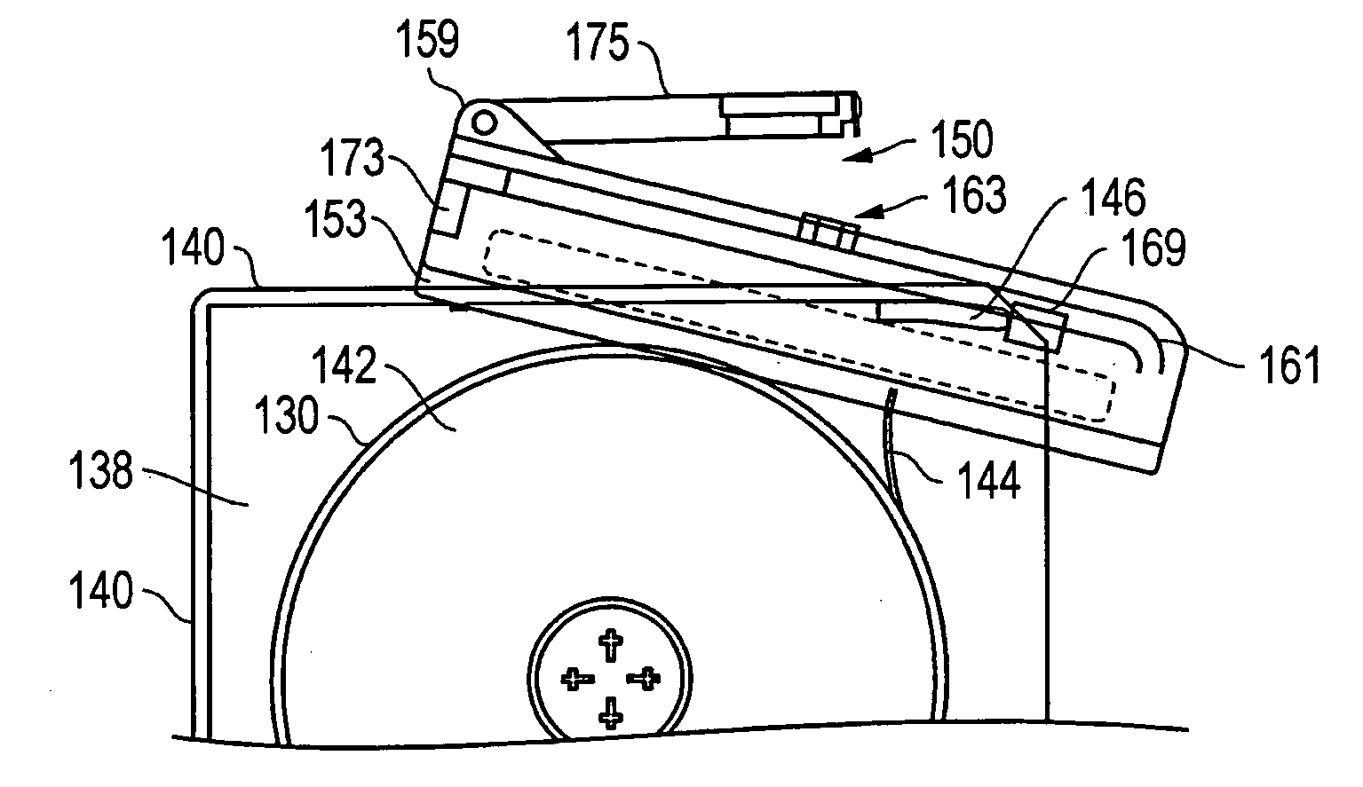
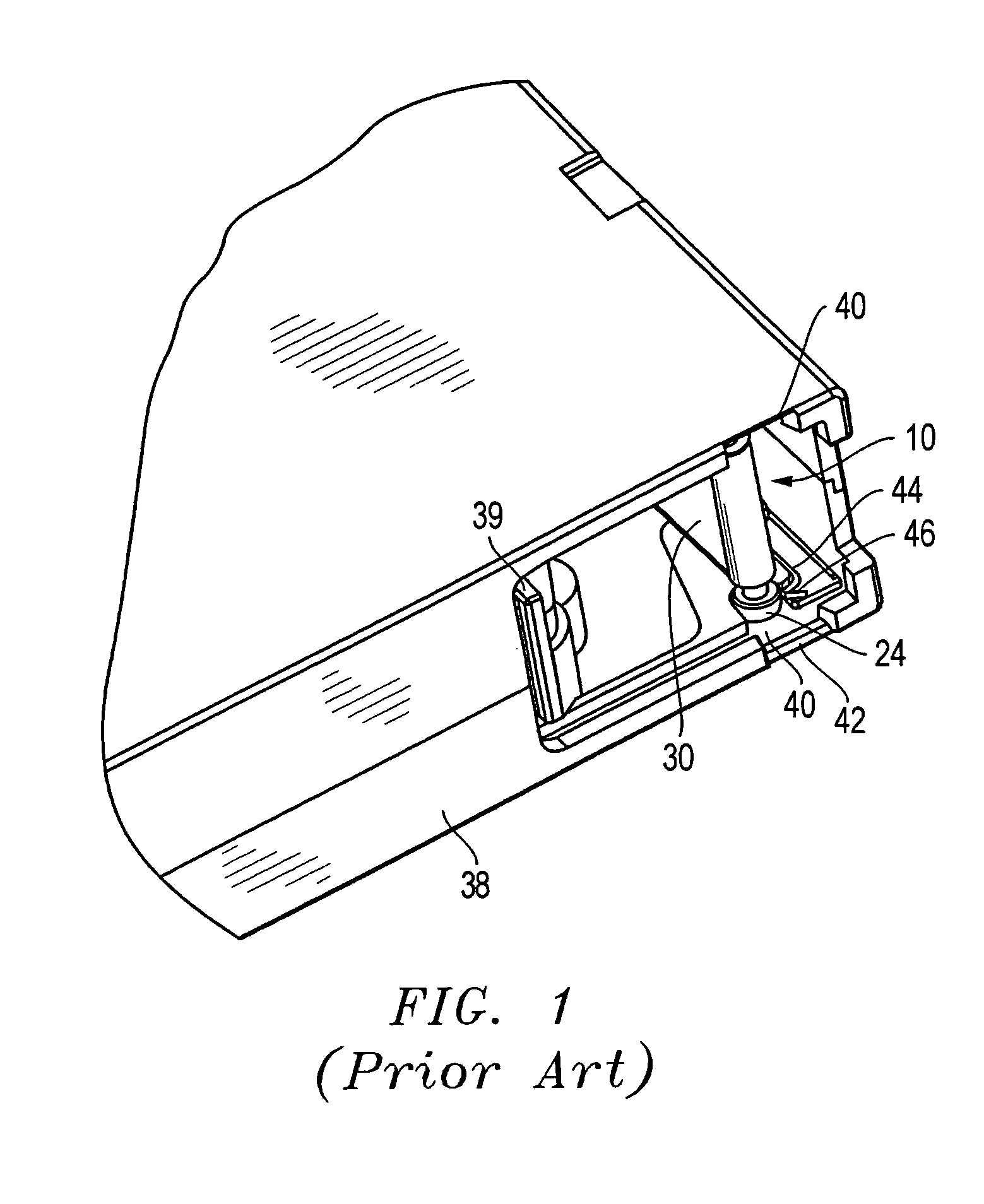
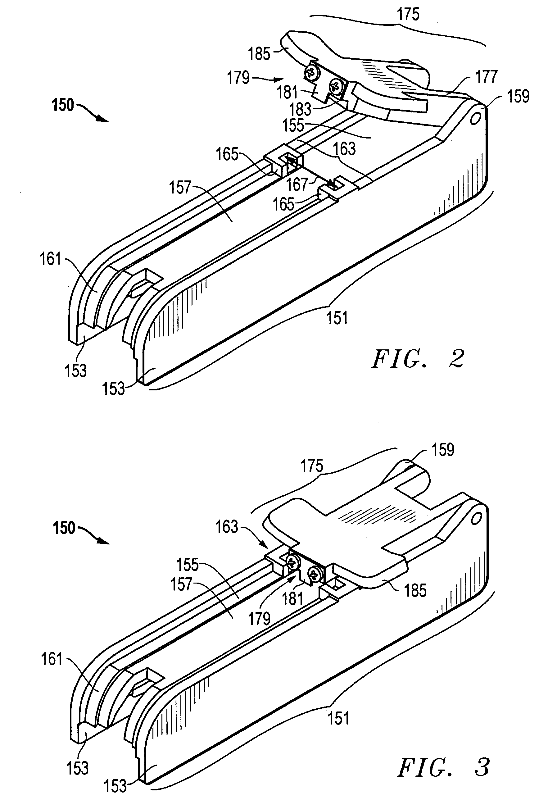
[0027]Referring to FIGS. 2–8, one embodiment of a system, method, and apparatus for attaching a leader pin to the data tape 130 of a data tape cartridge 138 with a tool 150 is disclosed. The leader pin may comprise, for example, a leader pin assembly having a leader pin 112 (FIGS. 7 and 8) and a retention clip 114 as is known in the art and generally described above with respect to FIG. 1. The data tape cartridge 138 (FIGS. 5 and 6) may comprise a conventional, generally rectangular design having edges 140 that are substantially planar. A spool 142 of the data tape 130 is located inside the data tape cartridge 138 and has a leader end 144. The cartridge 138 also has a movable door 146 for accessing the data tape 130 and is movable between an open position and a closed position. The door 146 is typically spring-biased to the closed position to better protect data tape 130 when cartridge 138 is not in use.

[0028]A system constructed in accordance with one embodiment of the present inve...


PUM

PropertyMeasurementUnit
acute angleaaaaaaaaaa
perimeteraaaaaaaaaa
shapeaaaaaaaaaa

Abstract

A tool for reattaching a leader pin assembly to the data tape of a data tape cartridge utilizes a base that snaps onto the cartridge body. The tool opens the door of the cartridge and the loose leader tape inside the cartridge is laid in an alignment channel. A leader pin is inserted into a set of receptacles over the tape, and a clip is inserted into a pocket within an arm on the tool. The tape is then folded and pulled down over the leader pin and held in the alignment channel with a finger of the user. The arm of the tool, which retains the clip, is then pivoted from a disengaged position to an engaged position. The clip snaps over a center section of the leader pin and the folded tape to form a leader pin assembly, thereby securing the tape in the leader pin assembly.

Description

BACKGROUND OF THE INVENTION[0001]1. Technical Field[0002]The present invention relates in general to an improved installation tool and method and, in particular, to an improved apparatus and method of attaching or re-attaching a leader pin assembly to the data tape of a data tape cartridge.[0003]2. Description of the Related Art[0004]Several systems and methods exist for winding various types of tape. In computer and audio / visual systems, data storage systems are provided to read data from and / or write data to data storage media, such as magnetic tape. The data storage systems utilizing magnetic tape data storage media typically contain sophisticated data processing equipment and mechanical assemblies which usually include a drive unit for winding the tape. Current tape winding systems use one or more spindles around which tape is wound. To move tape in such systems, a drive unit turns a first spindle in a first direction, thereby winding the tape from a second spindle onto the firs...

Claims


Application Information

Patent Timeline
Patent Type & Authority Patents(United States)
IPC IPC(8): G11B15/67G11B15/66
CPCG11B15/672Y10T29/49826Y10T29/49822Y10T29/49902Y10T29/537Y10T29/53465Y10T29/53909Y10T29/49895Y10T29/53913Y10T29/53978
Inventor WEST, RICHARD A.
Owner INT BUSINESS MASCH CORP
Why Eureka
Try Eureka