Electrical machine construction using axially inserted teeth in a stator ring or armature

a stator ring or armature technology, applied in the direction of stator/rotor body manufacturing, magnetic circuit shape/form/construction, magnetic bodies, etc., can solve the problems of high resistance, lower copper density, and difficulty in inserting or winding coils in one-piece stator slots

Inactive Publication Date: 2005-04-19
DURA TRAC MOTORS INC
View PDF17 Cites 40 Cited by
  • Summary
  • Abstract
  • Description
  • Claims
  • Application Information

AI Technical Summary

Problems solved by technology

Because of the physical structural restrictions, the resulting coils do not have precise parallel wound turns and tend to have longer wire lengths (causing higher resistance) and lower copper density.
In high current electrical machines that require large cross sectional areas of wire or buss bars, inserting or winding a coil in a one piece stator slot can be difficult or even impossible, due to the small access slot opening and the stiffness of the conductor used.

Method used


Image

  • Electrical machine construction using axially inserted teeth in a stator ring or armature
  • Electrical machine construction using axially inserted teeth in a stator ring or armature
  • Electrical machine construction using axially inserted teeth in a stator ring or armature

Examples


Embodiment Construction

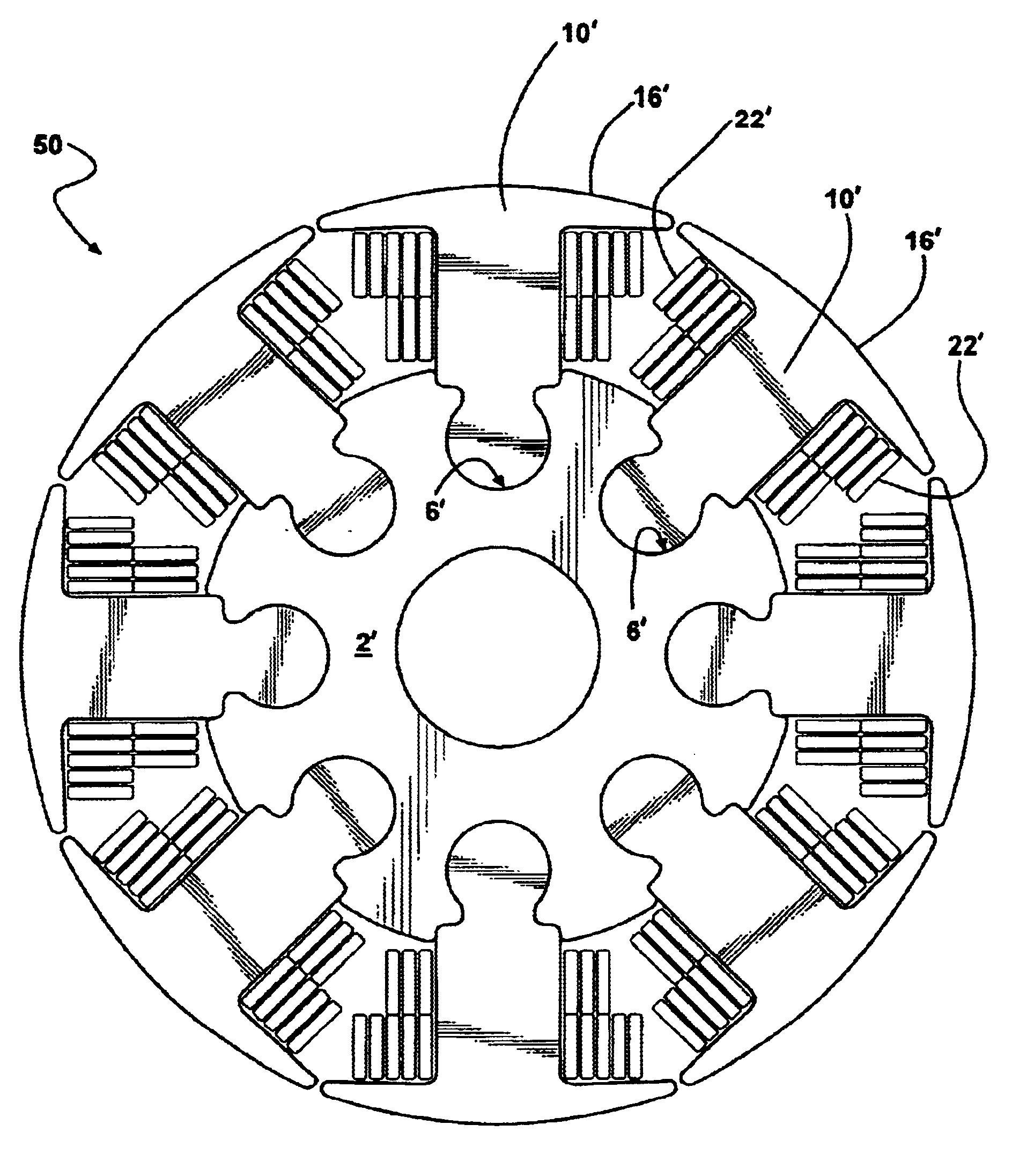
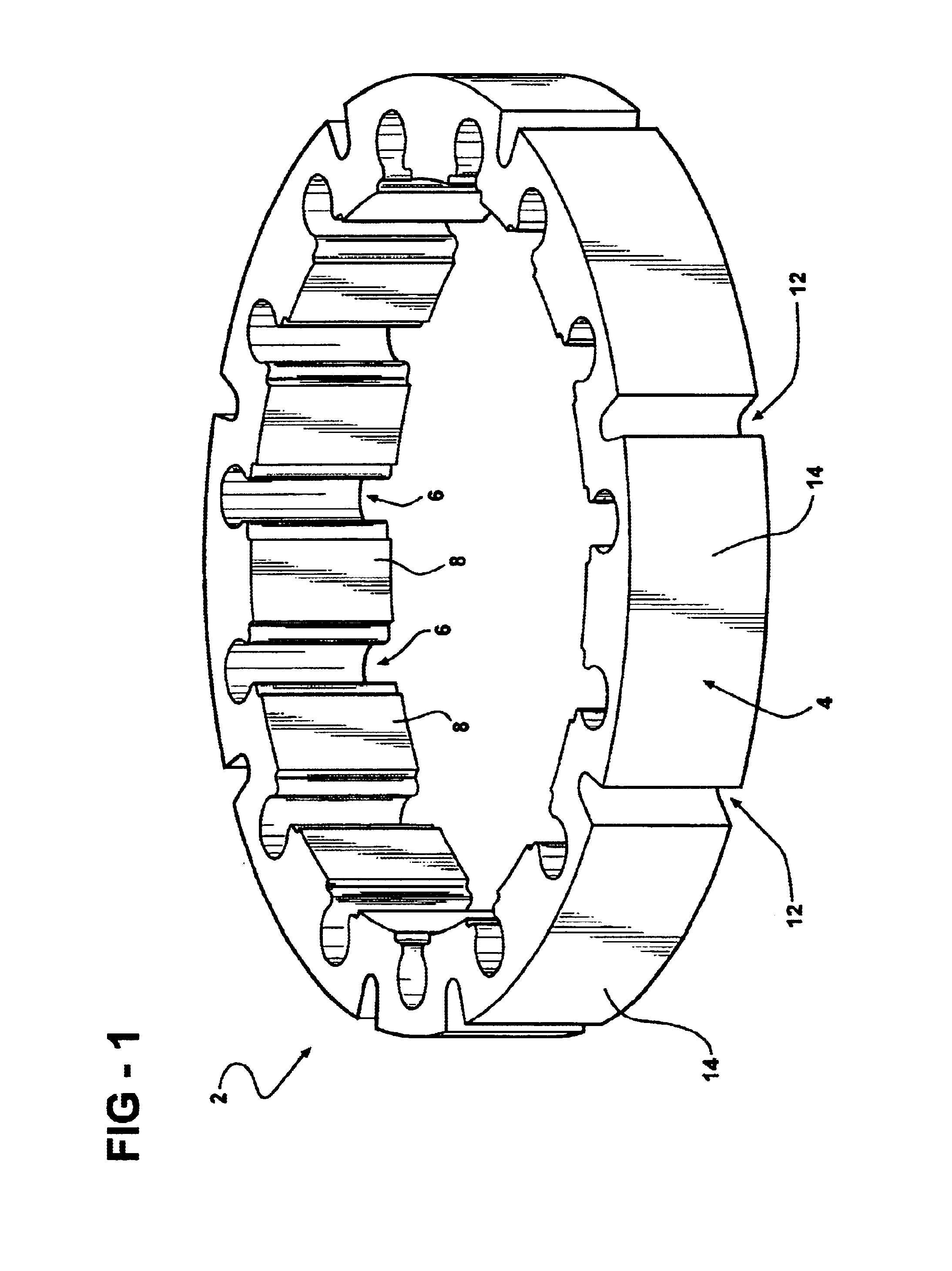
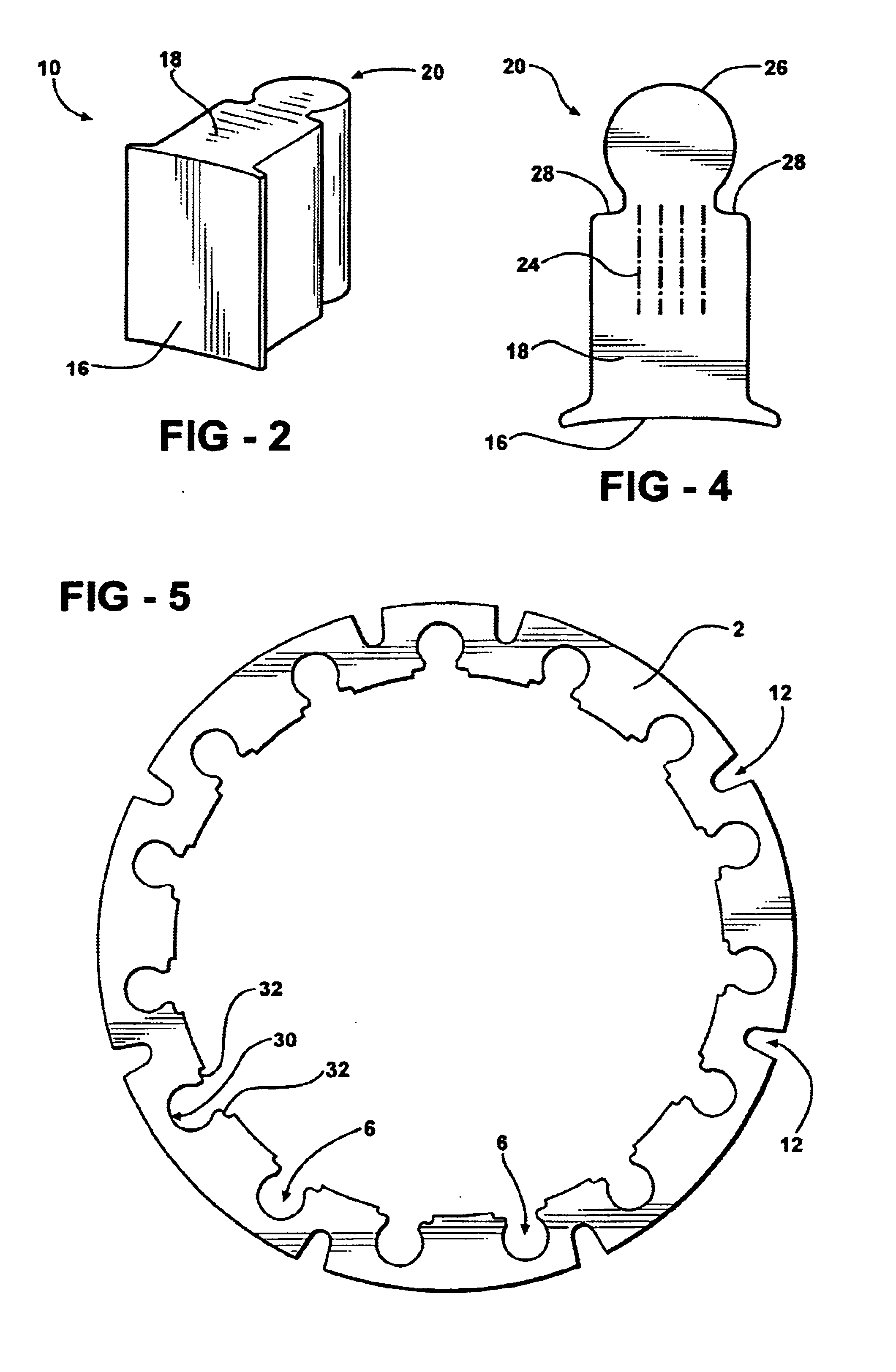
[0029]The present invention is directed to electrical machines that include stators or armatures which are configured to have a plurality of radially projecting teeth and coil windings supported on the teeth. Such electrical machines are exemplified by electrical motors, generators, alternators and other machines that produce or utilize rotational motion of a drive element. The present invention provides a construction design of a stator or armature that includes a stator ring or armature with separate teeth that can be inserted into slots in the stator ring or armature. The slots and teeth are configured so that the teeth can be axially inserted into the slots of the stator ring or armature and secured in fixed radially alignment. In the construction of stators the teeth are arranged to project radially inward. In the construction of armatures, the teeth are arranged to project radially outward.

[0030]The axially insertable teeth of the present invention can accept pre-wound coils w...


PUM

PropertyMeasurementUnit
magnetic flux propertyaaaaaaaaaa
magnetic eddy current lossesaaaaaaaaaa
magnetic fieldsaaaaaaaaaa

Abstract

An electrical machine using a plurality of separate teeth that can be axially inserted into a stator ring or armature after receiving a bobbin or form wound coil. Each tooth contains a primary locating structure and a secondary locating structure which respectively set the radial position and the angular position of the teeth in a stator ring. This construction can also be used with internal motor armatures. The primary and secondary locating structures have a size equal to or smaller than the portion of the tooth that holds the coil. This allows insertion of a pre-wound coil over these features without interference. The use of separate stator or armature teeth that are press fitted into the stator ring or armature allows the use of coil types that could not be inserted into a one piece stator or armature and tooth materials with optimum magnetic properties.

Description

RELATED APPLICATIONS[0001]The present invention was first disclosed in the Disclosure Document filed in the United States Patent and Trademark Office on Aug. 14, 2000 and assigned Disclosure Document No. 478531. There have been no previously filed applications anywhere in the world.TECHNICAL FIELD[0002]The present invention relates to electrical machines having stators, armatures and similar structures which include radial projections supporting wire coils. More particularly, the present invention is directed to methods of constructing electrical machines having stators, armatures and similar structures and to such electrical machines.BACKGROUND ART[0003]The use of stacked steel lamina in the construction in electrical machines having rotor / stator elements has been found useful to reduce magnetic eddy current losses as the magnetic fields rise and fall within such machines. Laminated stators that are typically used in electric motors form the stationary exteriors of such motors and ...

Claims


Application Information

Patent Timeline
Patent Type & Authority Patents(United States)
IPC IPC(8): H02K1/14
CPCH02K1/148Y10T29/49009Y10T29/49078Y10T29/49073Y10T29/49071Y10T29/49012H02K2213/12
Inventor ZEPP, LAWRENCE P.HENDERSHOT, JR., JAMES R.
Owner DURA TRAC MOTORS INC
Why Eureka
Try Eureka