Board-to-board connector

a board-to-board connector and connector technology, applied in the direction of electrical discharge lamps, coupling device connections, electric discharge tubes, etc., can solve the problems of inability to realize stable interlocking between the receptacle and the plug, and the difficulty of ensuring a firmly engagement between the plug and the receptacle of the board-to-board connector, so as to reduce the stress acted on the terminal, ensure the connection, and reduce the stress

Inactive Publication Date: 2005-04-19
CHENG UEI PRECISION IND CO LTD
View PDF6 Cites 58 Cited by
  • Summary
  • Abstract
  • Description
  • Claims
  • Application Information

AI Technical Summary

Benefits of technology

[0008]Thus, a first objective of the present invention is to provide a board-to-board connector which comprises a receptacle and a plug. A stable interlock between the receptacle and the plug can be achieved and a terminal yield failure can be avoid through a pressed contact between a projection of a second terminal and a contact end of a first terminal.
[0009]A second objective of the present invention is to provide a board-to-board connector which comprises a receptacle and a plug. A stable interlock between the receptacle and the plug can be achieved and a terminal yield failure can be avoid through an engagement of a flange formed on a receptacle housing and a first wedge hole of a plug housing.
[0010]A third objective of the present invention is to provide a board-to-board connector which comprises a receptacle and a plug. A stable interlock between the receptacle and the plug can be achieved and a terminal yield failure can be avoid through an interlock of a locking portion arranged horizontally of a first terminal and a second wedge hole formed on a plug housing.
[0013]When the receptacle and the plug are in assembled condition, the lateral boards slide into the lodged channel, the projected portion inserts into the recess, the first spring contact portion pressed contacts the projection. Thereby a stable retention and interlock between the receptacle and the plug of the present invention can be achieved.
[0014]To attain the second object, the board-to-board connector of the present invention further provides a flange on inner surfaces of the side walls of the receptacle extending toward the lodged channel. The plug is shaped to have a first wedge hole formed on outer surface of the lateral boards thereof in according to the flange. When the plug inserts into the receptacle, the lateral boards slide into the lodged channel, the projected portion lodges in the recess. Thereby a horizontal relative movement of the receptacle and the plug is restricted. Simultaneously, the flange inserts into the first wedge hole to maintain the receptacle and plug fixed together thereby to prevent the receptacle and plug from a vertical relative movement. Thus, the board-to-board connector of the present invention achieves a stable interlock between the receptacle and the plug via an engagement of the receptacle housing and the plug housing, owing to the first and second terminal only have a small contact pressure therebetween. It is not necessary to provide an interlock force to interlock therebetween, so a stress acted on the terminal can be decrease and a terminal yield failure can be avoid.
[0015]To attain the third object, the first terminal of the present invention is provided with a retention portion extending upwardly from the first base portion and a locking portion formed on the retention portion extending parallel with the first base portion toward the first spring contact portion. The side walls define a plurality of receiving holes to receiving the retention portion. A partial portion of the side walls which is located between the lodged channel and each of the receiving holes is cut off to form a mounting channel which communicates with the lodged channel, the first slot, and the receiving hole respectively. The lateral boards of the plug form a plurality of second wedge holes on its outer surface in accordance with the second slots. When the plug inserts into the receptacle of the board-to-board connector, the lateral boards slide into the lodged channel, the projected portion lodges in the recess. Thereby, a horizontal relative movement of the receptacle and the plug is restricted. Simultaneously, the locking portion comes into the mounting holes and inserts into the second wedge holes to maintain the receptacle and the plug fixed together thereby to prevent the receptacle and the plug from a vertical relative movement. Thus, the board-to-board connector of the present invention achieves a stable interlock between the receptacle and the plug via an engagement of the first terminal and the plug housing. A shorter moment arm of a pressed contact torque can be achieved for the first terminal due to arranging the locking portion horizontally, thereby a terminal yield failure can be avoid.

Problems solved by technology

In this consequence, however, it becomes difficult to ensure a firmly engagement between the plug and the receptacle of the board-to-board connector.
As a result, the locking member 51 may be broken or yielded due to a large stress resulted from the large force, further it can't realize a stable interlock between the receptacle and the plug.

Method used


Image

  • Board-to-board connector
  • Board-to-board connector
  • Board-to-board connector

Examples


first embodiment

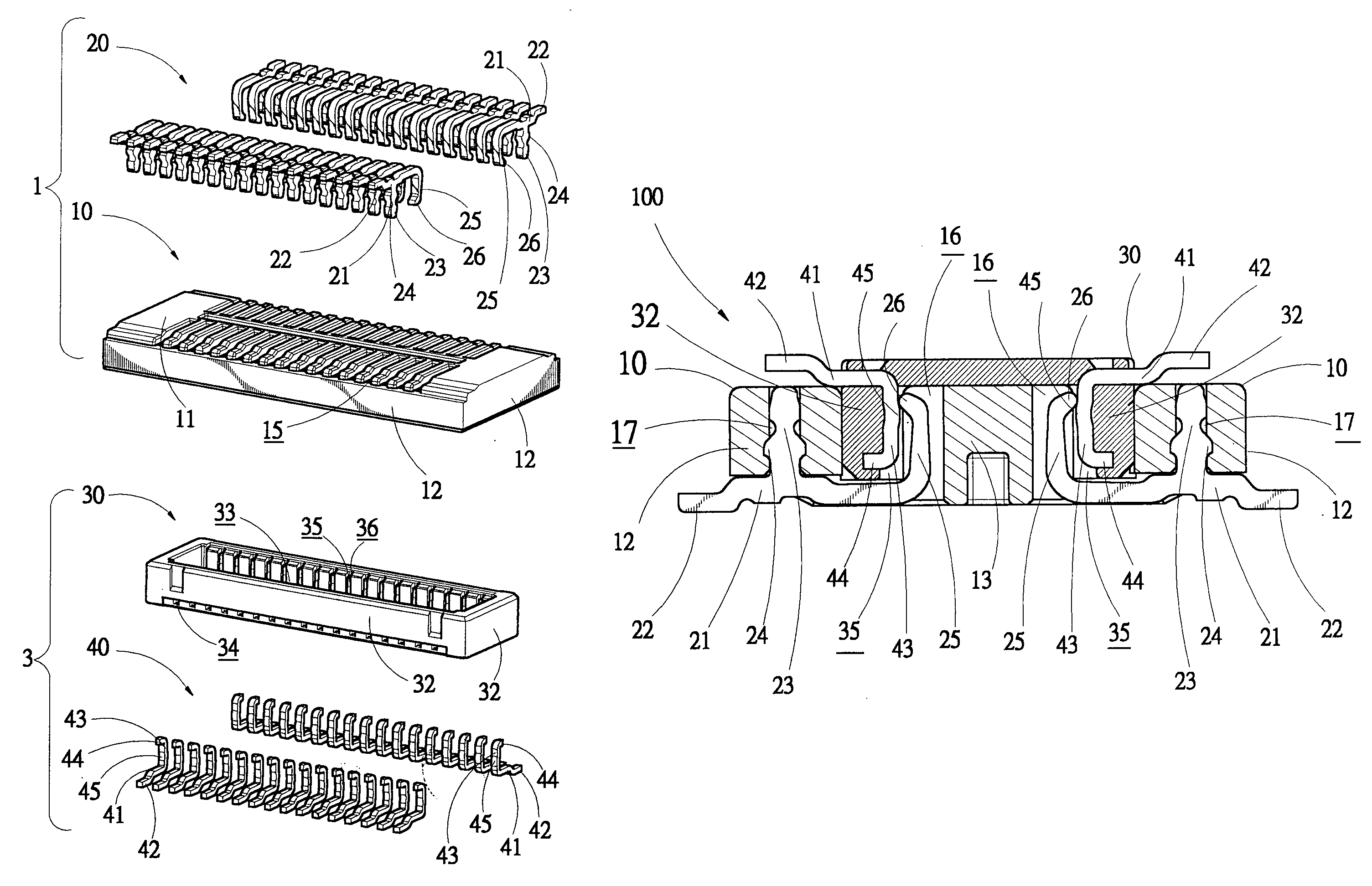
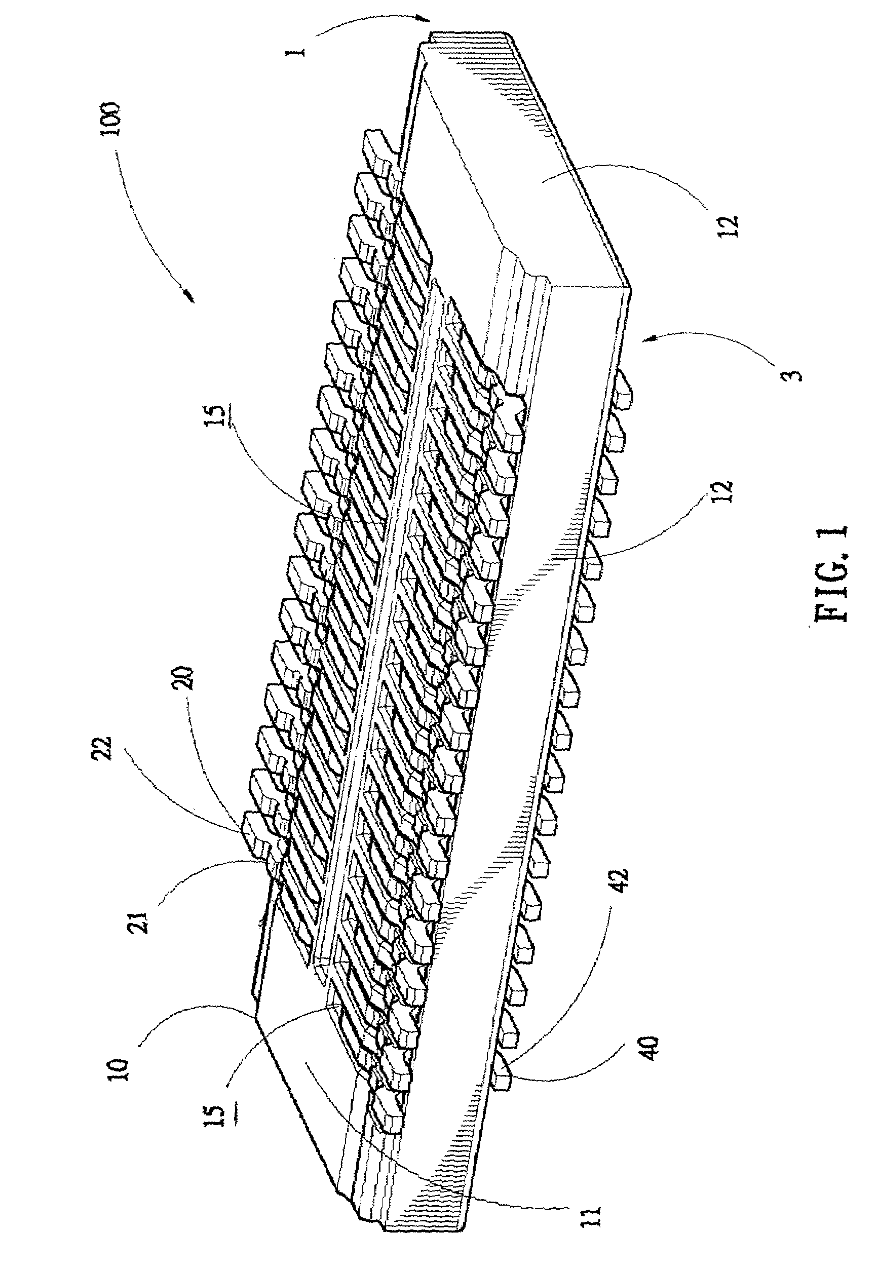
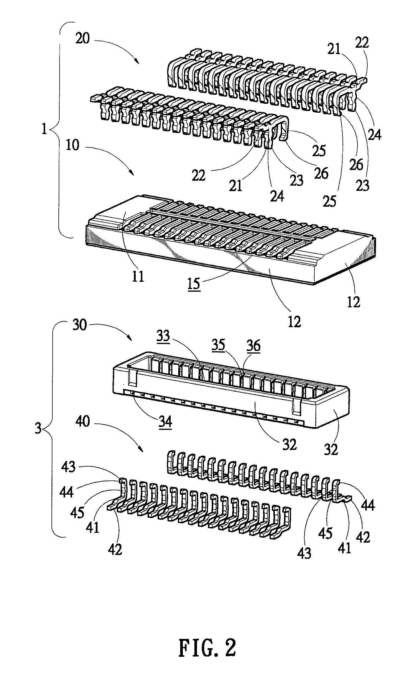
[0031]As shown in FIG. 1 to FIG. 3, a board-to-board connector in accordance with the present invention is shown. The board-to-board connector generally designed with reference numeral 100 comprises a receptacle 1 and a plug 3 which are respectively of flat configurations for surface mounting on individual printed circuit boards (PCBs)(not shown) to interconnect circuits on the boards.

[0032]With reference to FIGS. 4 and 5, the receptacle 1 includes a receptacle housing 10 receiving a plurality of first terminals 20 in two parallel arrays. The receptacle housing 10 is of a flat rectangular configuration to have a flat base 11. Side walls 12 are projected vertically from edges of the flat base 11. A projected portion 13 extends upwardly from a middle portion of the flat base 11 to define a lodged channel 14 with the side walls 12 therebetween. Opposite sides of the flat base 11 form a plurality of evenly spaced fist slots 15 which extend outwardly through the flat base 11 for holding ...

second embodiment

[0043]Referring now to FIGS. 10 to 12, the present invention is described. The receptacle 1 is further provided with a plurality of flanges 18 on inner surfaces of the side walls 12′ extending toward the lodged channel 14. The plug 3 is shaped to have a plurality of first wedge holes 37 formed on outer surfaces of the lateral board 32′ thereof in accordance with the flanges 18.

[0044]When the plug 3 inserts into the receptacle 1 of the board-to-board connector 100 of the second embodiment, the lateral boards 32′ slide into the lodged channel 14, the projected portion 13 lodges in the recess 33, thereby a horizontal relative movement of the receptacle 1 and the plug 3 is restricted. Simultaneously, each of the flanges 18 correspondingly wedges into each of the first wedge hole 37 to maintain the receptacle 1 and the plug 3 fixed together, thereby to prevent the receptacle 1 and the plug 3 from a vertical relative movement. Thus the board-to-board connector 100 of the second embodiment...

third embodiment

[0045]Referring now to FIG. 13, the present invention is shown. The retention portion 23 of the first terminal 20′ is provided additionally with a locking portion 27 extending parallel with the first base portion 21 toward the first spring contact terminal 25. A partial portion of the side walls 12″ located between the lodged channel 14. Each of the receiving holes 17 is cut off to form a mounting groove 19 which communicates with the lodged channel 14, the first slot 15, and the receiving hole 17 respectively. The lateral boards 32″ of the plug 3 form a plurality of second wedge holes 38 on its outer surface in accordance with the second slots 34.

[0046]When the plug 3 inserts into the receptacle 1 of the board-to-board connector 100 of the third embodiment, the lateral boards 32″ slide into the lodged channel 14, the projected portion 13 lodges in the recess 33, thereby a horizontal relative movement of the receptacle 1 and the plug 3 is restricted. Simultaneously, the locking por...


PUM


Abstract

A board-to-board connector comprises a receptacle and a plug. The receptacle is composed of a receptacle housing and a plurality of first terminals parallelized. The plug is also composed of a plug housing and a plurality of second terminals parallelized. Meanwhile, the present invention provides a first design which forms a projection on the second terminal, a second design which defines a flange on the receptacle housing and a first wedge hole on the plug housing in accordance with the flange, and a third design which forms a retention portion and a locking portion on the first terminal and a second wedge hole on the plug housing in accordance with the locking portion, thereby avoiding terminals yield and providing a stable improved retention between the receptacle and the plug.

Description

BACKGROUND OF THE INVENTION[0001]1. Field of the Invention[0002]The present invention general relates to a board-to-board connector, and especially to a board-to-board connector having a receptacle and a plug which is capable of assuring a reliable interlock therebetween.[0003]2. The Related Art[0004]In the field of the electronics industry, in order to electrical connect two parallel printed circuit boards (PCBs), it is necessary to provide a surface mount miniature board-to-board connector which is composed of a receptacle with a plurality of first contacts and a plug with a plurality of second contacts. One end of the first and second contacts engages with each other, the other end of the first and second contacts connects to a printed circuit board respectively.[0005]At present, the trend of consumer electronics such as a mobile telephone or a digital still camera constantly reduces its size. The board-to-board connector used in the miniaturization consumer electronic devices is...

Claims


Application Information

Patent Timeline
Patent Type & Authority Patents(United States)
IPC IPC(8): H01R12/00H01R12/71
CPCH01R12/716H01R12/7082
Inventor HUANG, CHUNG-HSINPENG, YUNG-CHICHIANG, SHU-MAN
Owner CHENG UEI PRECISION IND CO LTD
Why Eureka
Try Eureka