RF filtered DC interconnect
a dc interconnect and filtering technology, applied in the field of rf filtered dc interconnect, can solve the problems of not tolerating a large tolerance variation in and/or requiring an additional wire bond
- Summary
- Abstract
- Description
- Claims
- Application Information
AI Technical Summary
Benefits of technology
Problems solved by technology
Method used
Image
Examples
Embodiment Construction
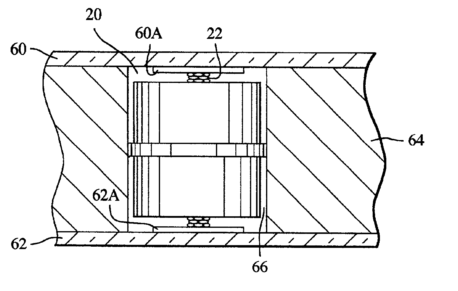
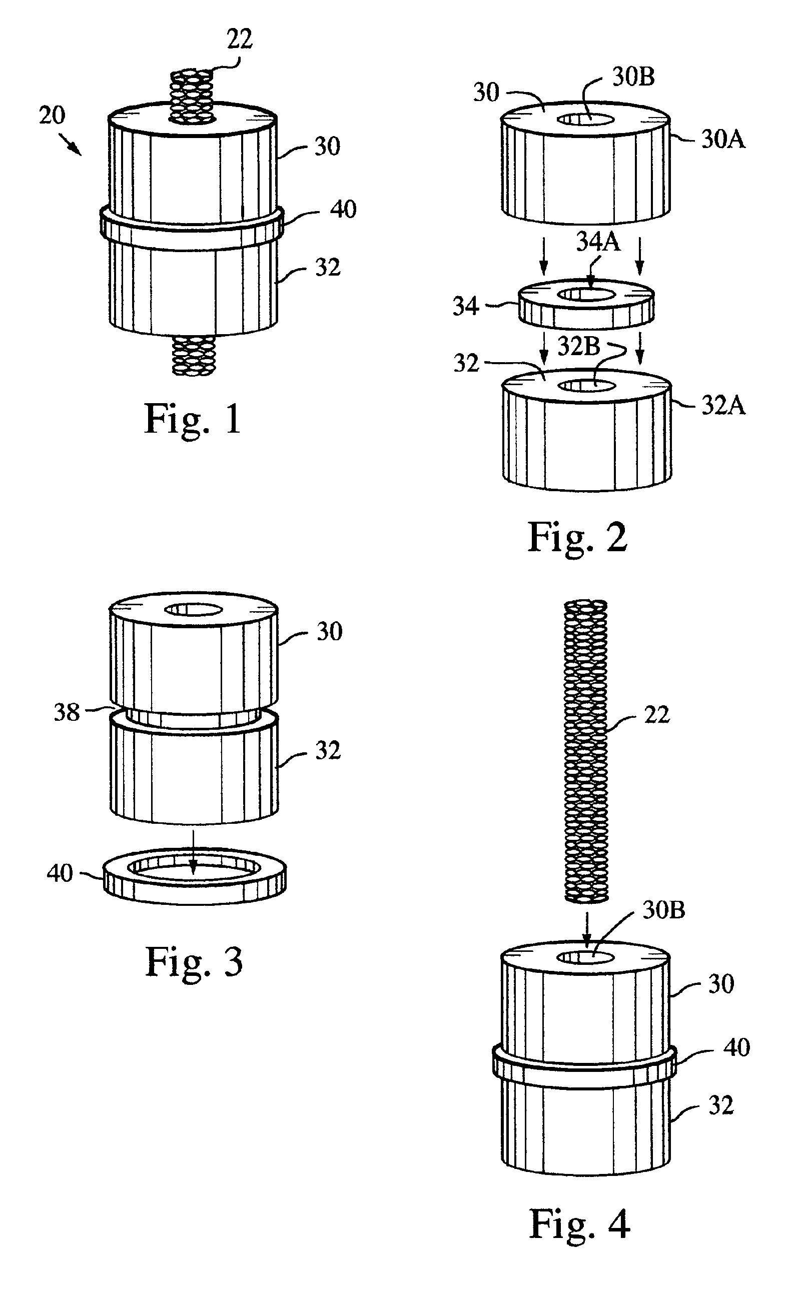
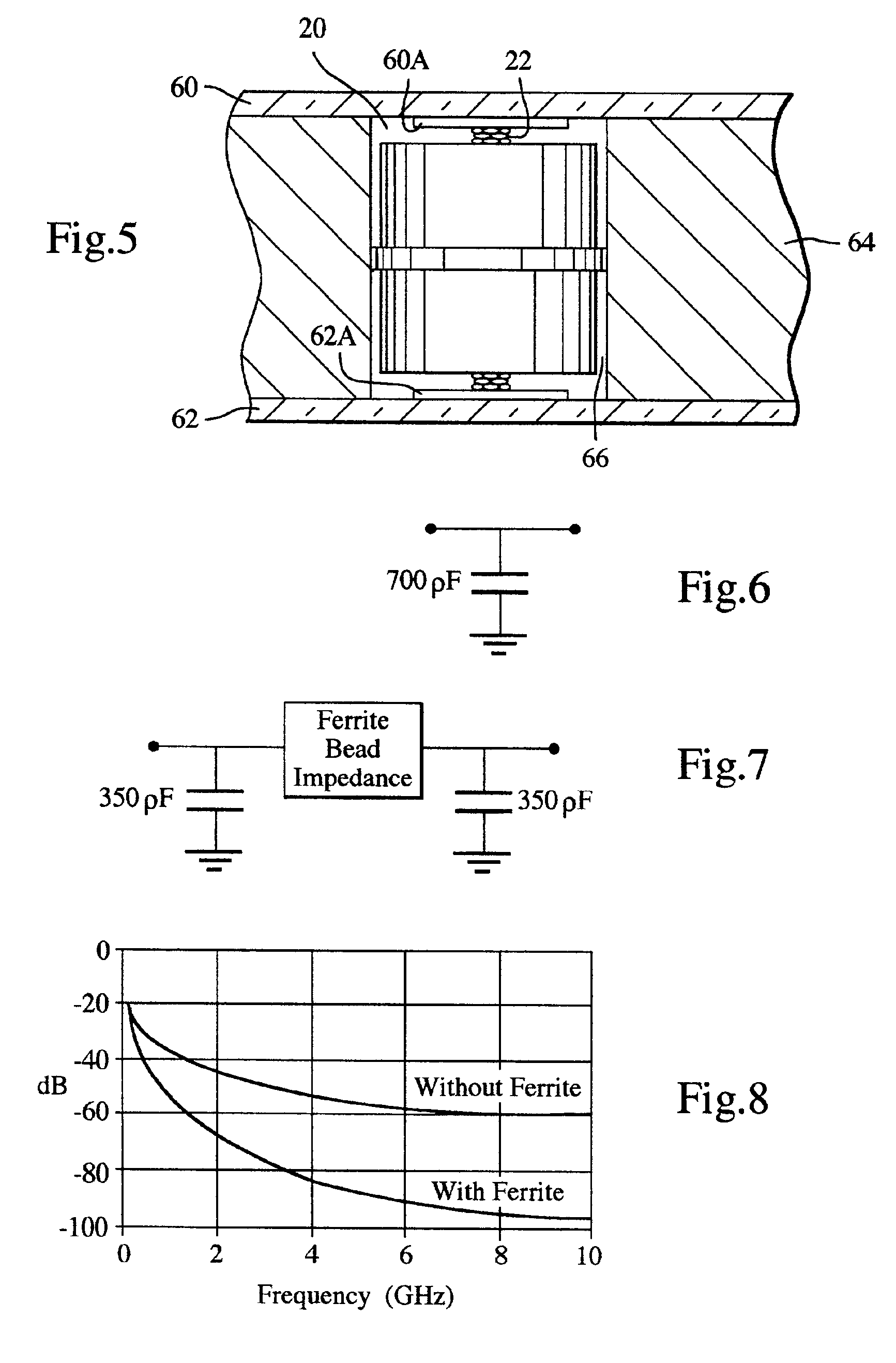
[0011]An embodiment of a filtered “button” DC interconnect between circuit boards employs a finely wound wire mesh imbedded within a series of dielectric and ferrite cylinders. An exemplary embodiment of a filtered button DC interconnect structure 20 is illustrated in FIGS. 1-4. The structure employs a finely wound wire mesh structure 22 imbedded within a series of dielectric and ferrite cylinders. FIG. 1 is an isometric view of the structure 20. FIGS. 2-4 are respective isometric partial exploded views, illustrating assembly of the structure and its constituent parts. The wire mesh interconnect 20 is captivated within the button structure to prevent movement and ensure proper contact with the mating surfaces. In addition, the interconnect serves as an RF filter by providing rejection of RF and microwave frequencies between the interconnected circuits 60, 62 (FIG. 5). The interconnect structure 20 accommodates wide assembly tolerances while maintaining excellent electrical contact. ...
PUM
 Abstract
Description
Claims
Application Information
 - R&D
- Intellectual Property
- Life Sciences
- Materials
- Tech Scout
- Unparalleled Data Quality
- Higher Quality Content
- 60% Fewer Hallucinations
Browse by: Latest US Patents, China's latest patents, Technical Efficacy Thesaurus, Application Domain, Technology Topic, Popular Technical Reports.
© 2025 PatSnap. All rights reserved.Legal|Privacy policy|Modern Slavery Act Transparency Statement|Sitemap|About US| Contact US: help@patsnap.com


