
Microwave filter with adaptive predistortion

a filter and microwave technology, applied in the field of filters, can solve the problems of performance degradation, 5.7 db extra insertion loss, and only 3.8 db insertion loss

Inactive Publication Date: 2005-04-19
HONEYWELL LIMITED HONEYWELL LIMITÉE
View PDF8 Cites 21 Cited by
  • Summary
  • Abstract
  • Description
  • Claims
  • Application Information

AI Technical Summary

Benefits of technology

[0019]In yet another aspect, the present invention provides an adaptively predistorted filter, the filter having an initial transfer function comprising a plurality of poles at initial locations, wherein the poles are adaptively predistorted for allowing the adaptively predistorted filter to achieve specified performance criteria, the poles being adaptively predistorted by shifting the poles away from the initial locations, at least one of the poles being shifted by a unique amount relative to the shifting of the remaining poles.

Problems solved by technology

Accordingly, using the prior art predistortion method leads to an extra insertion loss of 5.7 dB, while the adaptive predistortion method increases the insertion loss by only 3.8 dB.
However, this leads to performance degradation as shown in FIGS. 8a and 8b (the frequency axis for FIGS. 8a to 11b are in MHz and centered at 4 GHz). FIG. 8a shows the group delay within the pass band of the OMUX filter 64.
The group delay is not flat within the passband and suffers severe degradation near the transition bands.
However, any extra insertion loss for the OMUX filter 64 introduced by adaptive predistortion is not desirable.

Method used


Image

  • Microwave filter with adaptive predistortion
  • Microwave filter with adaptive predistortion
  • Microwave filter with adaptive predistortion

Examples


Embodiment Construction

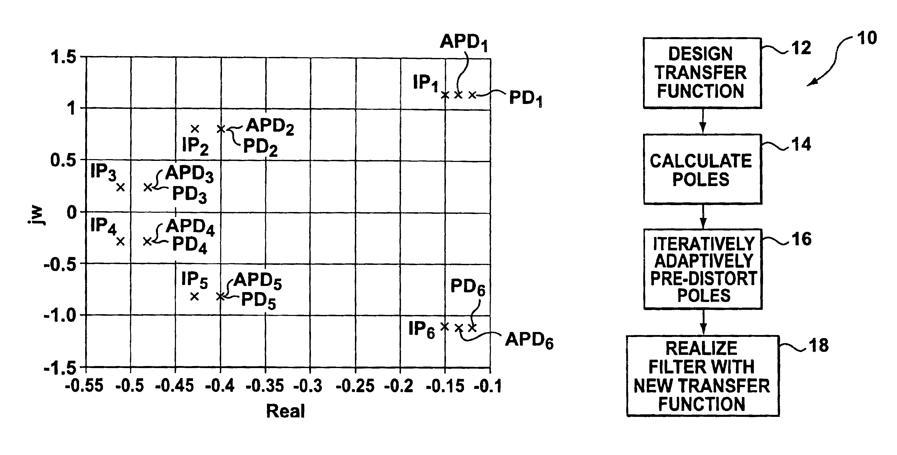
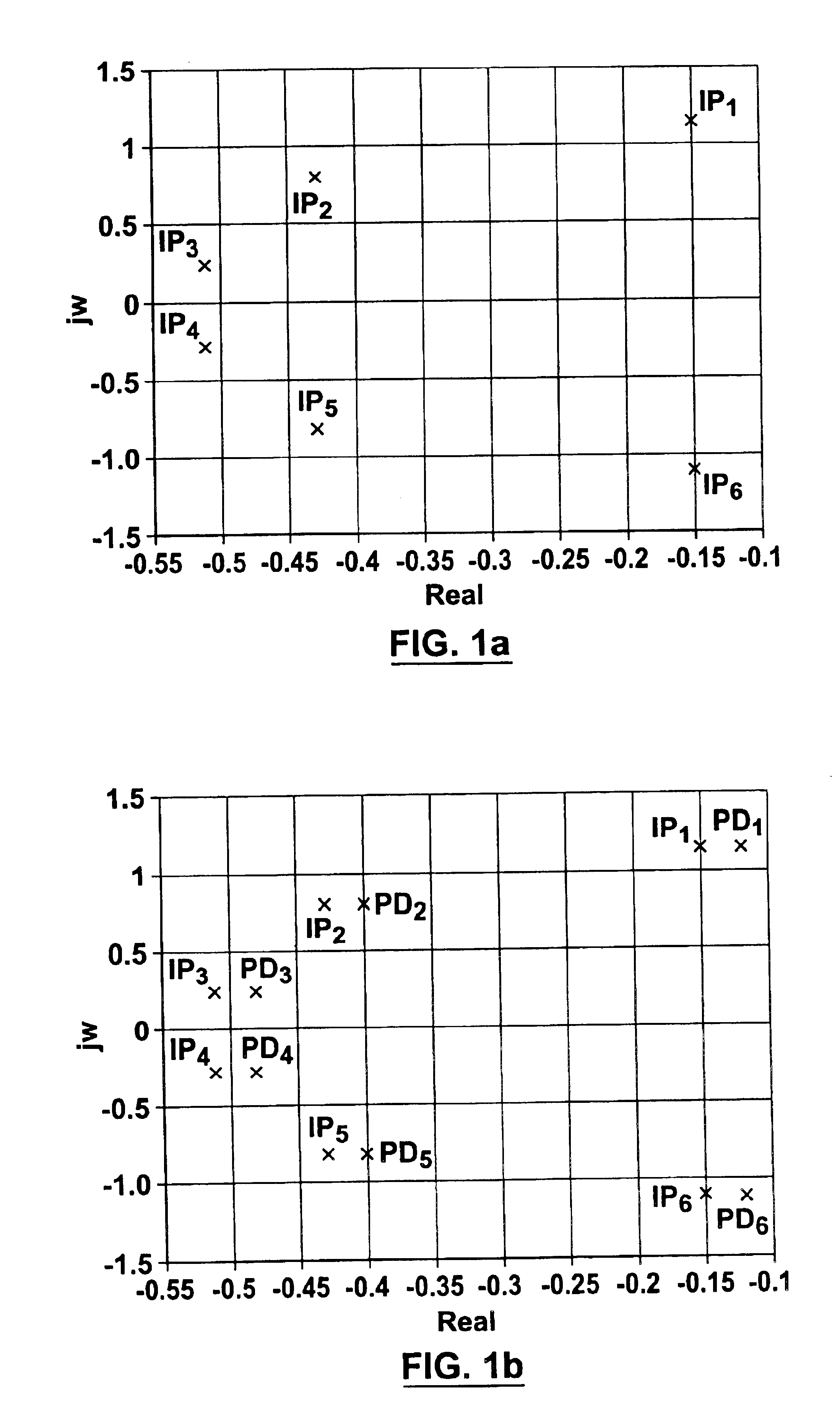
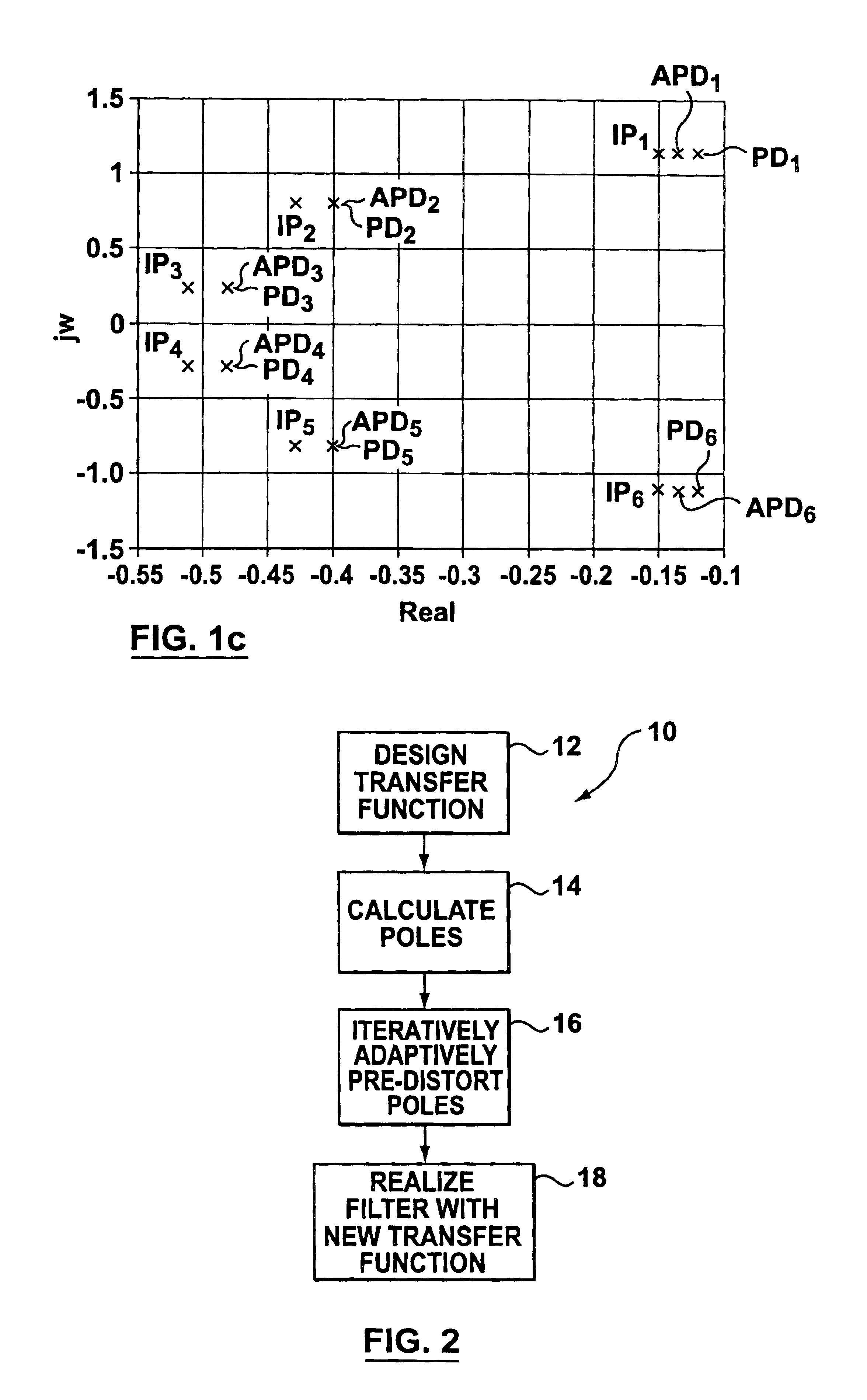
[0044]The inventors have realized that the predistortion method introduced by Livingston and Williams can be improved by removing the constraint that the poles must be shifted by the same amount. Accordingly, an adaptive predistortion method, in accordance with the present invention, involves predistorting the position of the poles in an adaptive fashion such that the position of at least some of the poles are shifted by differing amounts to improve at least one property of the realized filter such as insertion loss, group delay, etc. Alternatively, the method may involve adaptive predistortion for simultaneous improvement of amplitude and group delay.

[0045]The adaptive predistortion method may be applied to a filter that utilizes resonators with a high Q factor to improve the performance of the filter. Alternatively, the adaptive predistortion method may be applied to a filter that utilizes resonators with a low Q factor to allow the filter to emulate the performance of a high Q fa...


PUM


Abstract

The invention provides a method and apparatus for a adaptively predistorted filter which has a transfer function that satisfies performance criteria specified for at (east one property of the filter. The transfer function is obtained by adaptively predistorting the transfer function poles to meet the performance criteria such that at least one of the poles is shifted by a unique amount.

Description

FIELD OF THE INVENTION[0001]The invention relates to filters and more particularly to a method and apparatus for realizing a transfer function for a filter based on adaptive predistortion.BACKGROUND OF THE INVENTION[0002]A microwave filter is an electromagnetic circuit that can be tuned to pass energy at a specified resonant frequency. Accordingly, microwave filters are commonly used in telecommunication applications to transmit energy in a desired band of frequencies (i.e. the passband) and reject energy at unwanted frequencies (i.e. the stopband) that are outside of the desired band. In addition, the microwave filter should preferably meet some performance criteria for properties which typically include insertion loss (i.e. the minimum loss in the passband), loss variation (i.e. the flatness of the insertion loss in the passband), rejection or isolation (the attenuation in the stopband), group delay (i.e. related to the phase characteristics of the filter) and return loss.[0003]In...

Claims


Application Information

Patent Timeline
Patent Type & Authority Patents(United States)
IPC IPC(8): H01P1/20H01P1/205
CPCH01P1/2053H01P1/20
Inventor YU, MINGDOKAS, VANTANG, WAI-CHEUNG
Owner HONEYWELL LIMITED HONEYWELL LIMITÉE
Learn More