
Portable information terminal

Inactive Publication Date: 2005-04-19
PIONEER CORP +1
View PDF12 Cites 124 Cited by
  • Summary
  • Abstract
  • Description
  • Claims
  • Application Information

AI Technical Summary

Benefits of technology

[0010]It is therefore an object of the present invention to provide a portable information terminal capable of solving the problem of the “digital divide” deepening with the progress in multifunction design, and of enhancing security when a high volume of information accumulated is carried around.
[0045]With the portable information terminal of the fourteenth feature, since the communication between the primary and secondary terminals is based on the Bluetooth technology, it is possible to enhance security by means of authentication and encryption processing which are required in the Bluetooth technology. The communication of the communication element with the mobile communication network allows the secondary terminal to serve as a portable telephone, and to be connected to a computer network through the mobile communication network to provide the user with various services on the Internet.

Problems solved by technology

However, with the explosive progression of information technology, a disparity between persons in the degree of successful usage of the information terminals has widened, which has raised the serious problem associated with the so-called “digital divide” in which persons unskilled in handling the information terminals are falling behind in society in terms of jobs, income and the like.
For this requirement, a multifunction design for portable information terminals will need to be further progressed to increase the number of available functions, and in consequence the manipulation thereof will be further complicated, which must make the problem of the “digital divide” even more significantly serious.
In addition, such progress in multifunction design will enable a single portable information terminal to accumulate various kinds of information including personal information, which produces another serious problem of how to ensure security when a high volume of information accumulated is carried around.

Method used


Image

  • Portable information terminal
  • Portable information terminal
  • Portable information terminal

Examples


Embodiment Construction

[0063]A preferred embodiment according to the present invention will be described hereinafter in detail with reference to the accompanying drawings.

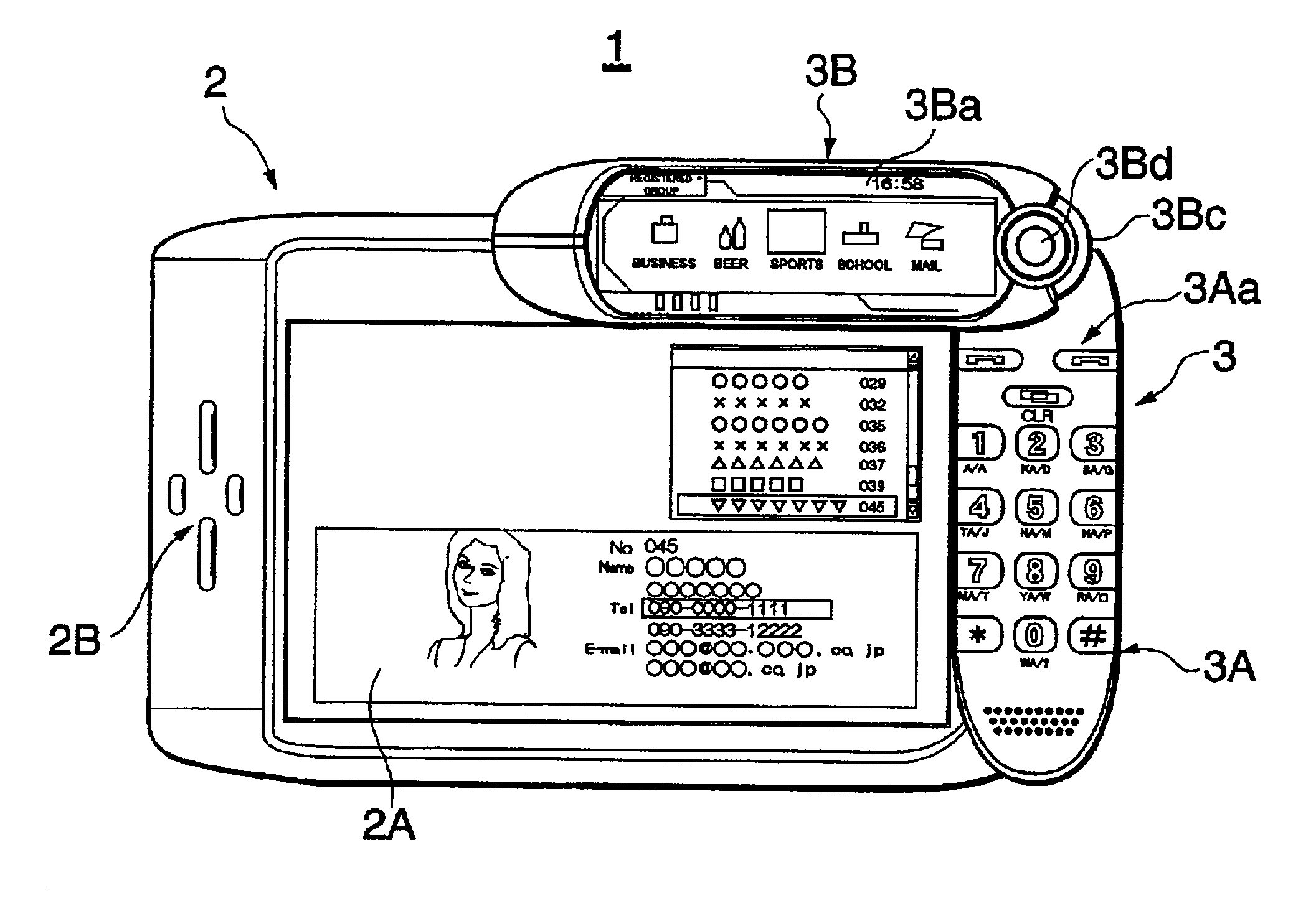
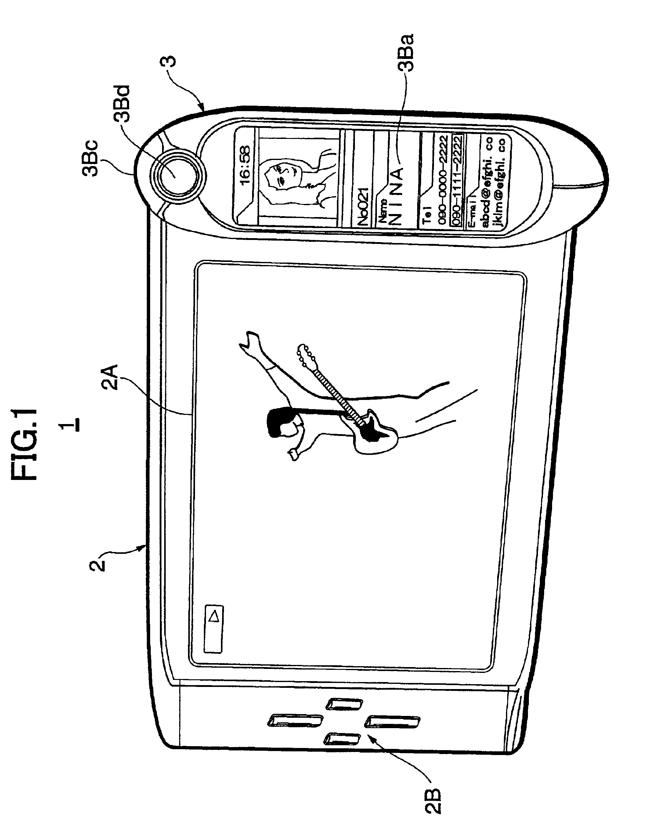
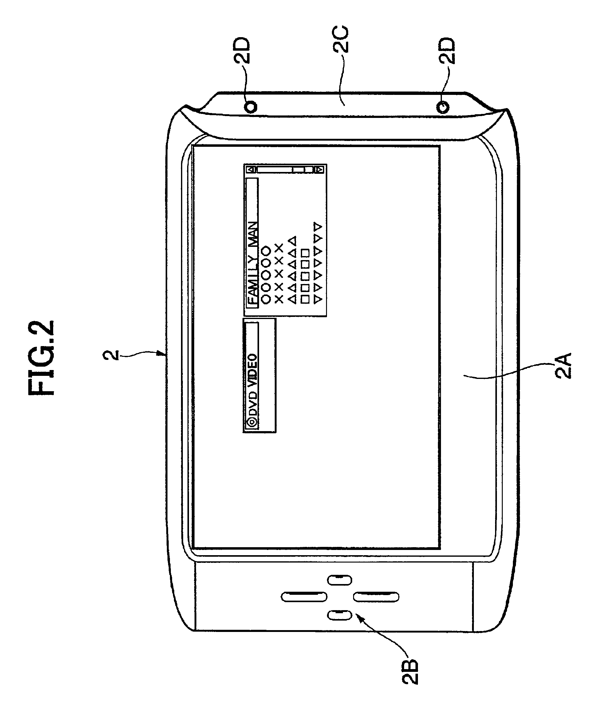
[0064]FIG. 1 is a perspective view illustrating an example of portable information terminal according to a preferred embodiment of the present invention. FIG. 2 is a front view illustrating a primary terminal forming part of the portable information terminal in FIG. 1. FIG. 3 is a rear view illustrating the primary terminal. FIG. 4 is a front view illustrating a secondary terminal forming part of the portable information terminal in one of its usage patterns. FIG. 5 is a rear view of the secondary terminal.

[0065]In FIG. 1, the portable information terminal 1 is constructed of two parts, a primary terminal 2 and a secondary terminal 3 separably combined with the primary terminal 2.

[0066]As illustrated in FIG. 2, the primary terminal 2 has a substantially quadrangular plate-shaped outside shape, on the front surface of which a display pane...


PUM


Abstract

A portable information terminal 1 includes a primary terminal 2 and a secondary terminal 3 which are combinable and separable from each other, and individually have displays 2A, 3Ba, operation keys 2B, 3Aa, RAMs 24, 36, antennas 26, 37, and CPUs 20, 30. The RAMs 24, 36 of the respective terminals 1, 2 store application programs and the CPUs 20, 30 individually control to operate a required function and display an image on the displays 2A, 3Ba. The CPUs 20, 30 are connected through communication between the antennas 26, 37 to systematically share an operation for a required function and to display images associated with each other on the respective displays 2A and 3Ba.

Description

BACKGROUND OF THE INVENTION[0001]1. Field of the Invention[0002]This invention relates to an information terminal which is capable of being installed with functions distributed for carrying.[0003]The present application claims priority from Japanese Application No. 2001-189912, the disclosure of which is incorporated herein by reference for all purposes.[0004]2. Description of the Related Art[0005]In recent years, various types of portable information terminals such as a notebook-type personal computer, a PDA, a portable telephone and the like have become rapidly and widely available. Along with this, a variety of functions installed on portable information terminals for information processing have become rapidly enhanced.[0006]However, with the explosive progression of information technology, a disparity between persons in the degree of successful usage of the information terminals has widened, which has raised the serious problem associated with the so-called “digital divide” in w...

Claims


Application Information

Patent Timeline
IPC IPC(8): G06F1/16H04M1/725H04M1/02H04M1/72H04M1/00H04M1/72409H04M1/72412H04M11/00H04W28/00H04W88/02
CPCG06F1/1622G06F1/1626G06F1/1632G06F1/1677G06F1/1686H04M1/7253H04M1/0233H04M1/0243H04M1/72527G06F1/1698G06F2200/1614H04M1/0229H04M1/72412H04M1/72409H04M1/724092
Inventor HIRAYAMA, NAOFUMISUMA, DAISUKETOMONO, MIZUKIFUNAYAMA, TATSUFUMI
Owner PIONEER CORP
Learn More