Toy vehicle slot track

a technology for toy vehicles and slot tracks, which is applied in the direction of toys, ways, constructions, etc., can solve the problem of not providing power to the toy vehicles

Inactive Publication Date: 2005-04-26
MATTEL INC
View PDF16 Cites 32 Cited by
  • Summary
  • Abstract
  • Description
  • Claims
  • Application Information

AI Technical Summary

Benefits of technology

[0006]According to a second aspect of the invention, a toy vehicle slot track race set comprising a pair of toy race vehicles is disclosed. The toy race vehicles are essentially equal in width, and each toy race vehicle has a guide pin and a motor. At least one track section has an upper surface provided with a pair of non-intersecting guide slots. Each guide slot is provided with a pair of exposed power supply rails located so as to supply power to the motor of each toy race vehicle. The toy race vehicles are guided across the at least one track section by movement of the guide pin within the guide slot. The guide slots are spaced apart at a spacing which is less than a maximum width of each of the toy race vehicles.
[0007]According to yet a third aspect of the invention, a toy vehicle slot track for use with toy racing vehicles having a maximum width is disclosed. The track comprises an upper surface, with a plurality of separate guide slots disposed within the upper surface. The track further comprises a pair of power supply rails provided for each guide slot. The power supply rails are disposed within the upper surface on opposing sides of each guide slot. An adjoining pair of the plurality of guide slots in a first portion of the track are generally parallel and spaced apart at a first spacing which is greater than the maximum width of the toy racing vehicles. An adjoining pair of the plurality of guide slots in a second portion of the track are generally parallel and spaced apart at a second spacing which is less than the maximum width of the toy racing vehicles. A pair of the guide slots in a third portion of the track transition from the first spacing to the second spacing, while a pair of the guide slots in a fourth portion of the track transitioning from the second spacing to the first spacing. The pair of power supply rails run generally parallel to each guide slot at a generally uniform distance from each guide slot in each of the four portions of the track. A first length of the track may be formed by combining the first, third, second, fourth and first portions of the track in sequence.
[0008]According to still yet a fourth aspect of the invention, a toy vehicle slot track race set comprises a pair of toy race vehicles, each toy race vehicle having a maximum width, the maximum widths being generally equal for the pair of the toy race vehicles. Each toy race vehicle has an electric motor and a guide pin. The race set further comprises a track with an upper surface, a plurality of separate, non-intersecting guide slots disposed within the upper surface, and the guide slots being sized to receive and permit movement of the guide pins within the guide slots to guide the toy race vehicles about the track. A pair of exposed power supply rails are provided for each guide slot, disposed on opposing sides of each guide slot and providing power to the electric motor of each toy race vehicle in one of the slots. A first portion of the track is formed from at least one generally straight track segment having a pair of guide slots arranged generally parallel to one another and spaced apart at a first spacing which is greater than the maximum width of the toy racing vehicles. A second portion of the track is formed from at least one curved track segment having a pair of guide slots disposed toward an inner radius of the at least one curved track segment and arranged generally parallel to one another and spaced apart at a second spacing which is less than the maximum width of the toy racing vehicles. The pair of guide slots are disposed between two pairs of exposed power supply rails, and also a third guide slot is arranged to mate with one of the guide slots of the first portion of the track. A third portion of the track is formed from at least one generally straight track segment with a first end where a pair of guide slots are arranged to mate with the arrangement of the guide slots of the first portion of the track and with a second end where the pair of guide slots are arranged to mate with the arrangement of the pair of guide slots of the second portion of the track. A fourth portion of the track is formed from at least one generally straight track segment with a first end where a pair of guide slots are arranged to mate with the arrangement of the pair of guide slots of the second portion of the track and with a second end where the pair of guide slots are arranged to mate with the arrangement of the guide slots of the first portion of the track. The pair of power supply rails run generally parallel to each guide slot at a generally uniform distance from each guide slot in each of the four portions of the track.
[0009]The foregoing summary, as well as the following detailed description of preferred embodiments of the invention, will be better understood when read in conjunction with the appended drawings. For the purpose of illustrating the invention, there is shown in the drawings embodiments which are presently preferred. It should be understood, however, that the invention is not limited to the precise arrangements and instrumentalities shown. In the drawings:

Problems solved by technology

However, a scenario which is not replicated in the prior art is a “squeeze” maneuver seen in automobile racing, wherein the toy vehicles receive power during the maneuver.
However, the invention of U.S. Pat. No. 5,075,515 does not provide power to the toy vehicles as the toy vehicles move through the turn with the converged slots.

Method used


Image

  • Toy vehicle slot track
  • Toy vehicle slot track
  • Toy vehicle slot track

Examples


Embodiment Construction

[0014]Certain terminology is used in the following description for convenience only and is not limiting. The words “right”, “left”, “top”, and “bottom” designate directions in the drawings to which reference is made. The words “interior” and “exterior” refer to directions toward and away from, respectively, the geometric center of the toy vehicle slot track and designated parts thereof. The terminology includes the words above specifically mentioned, derivatives thereof and words of similar import.

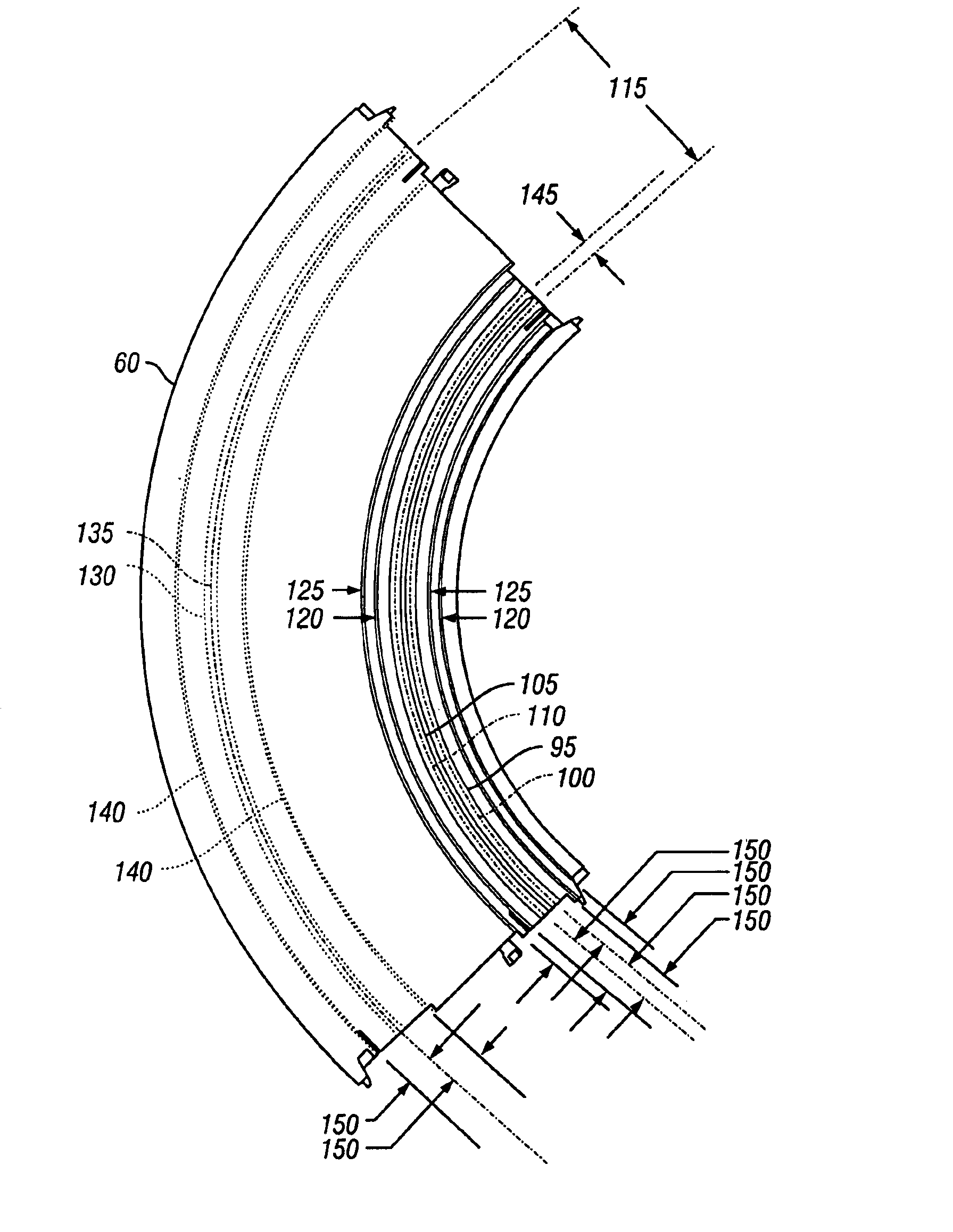
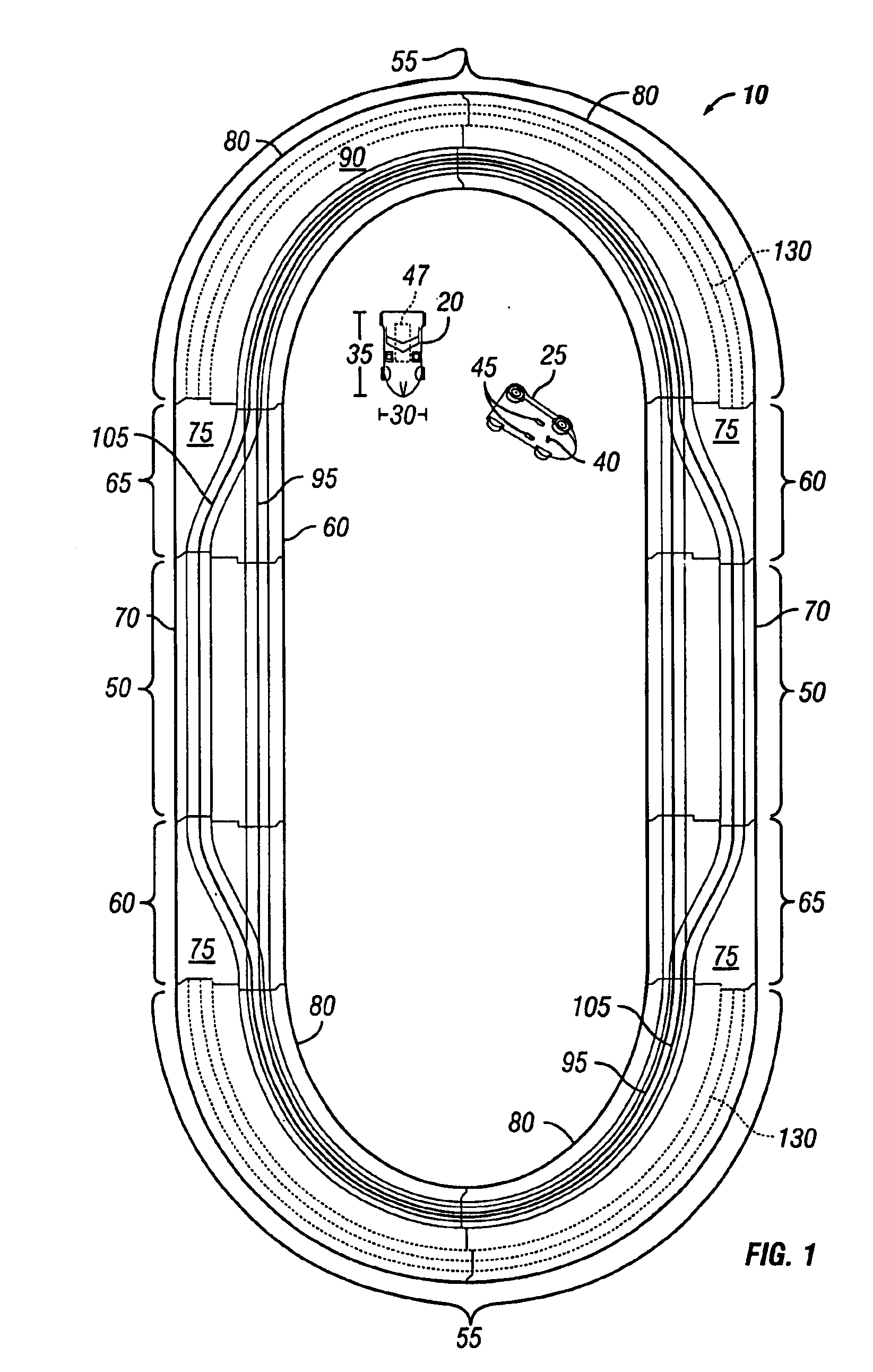
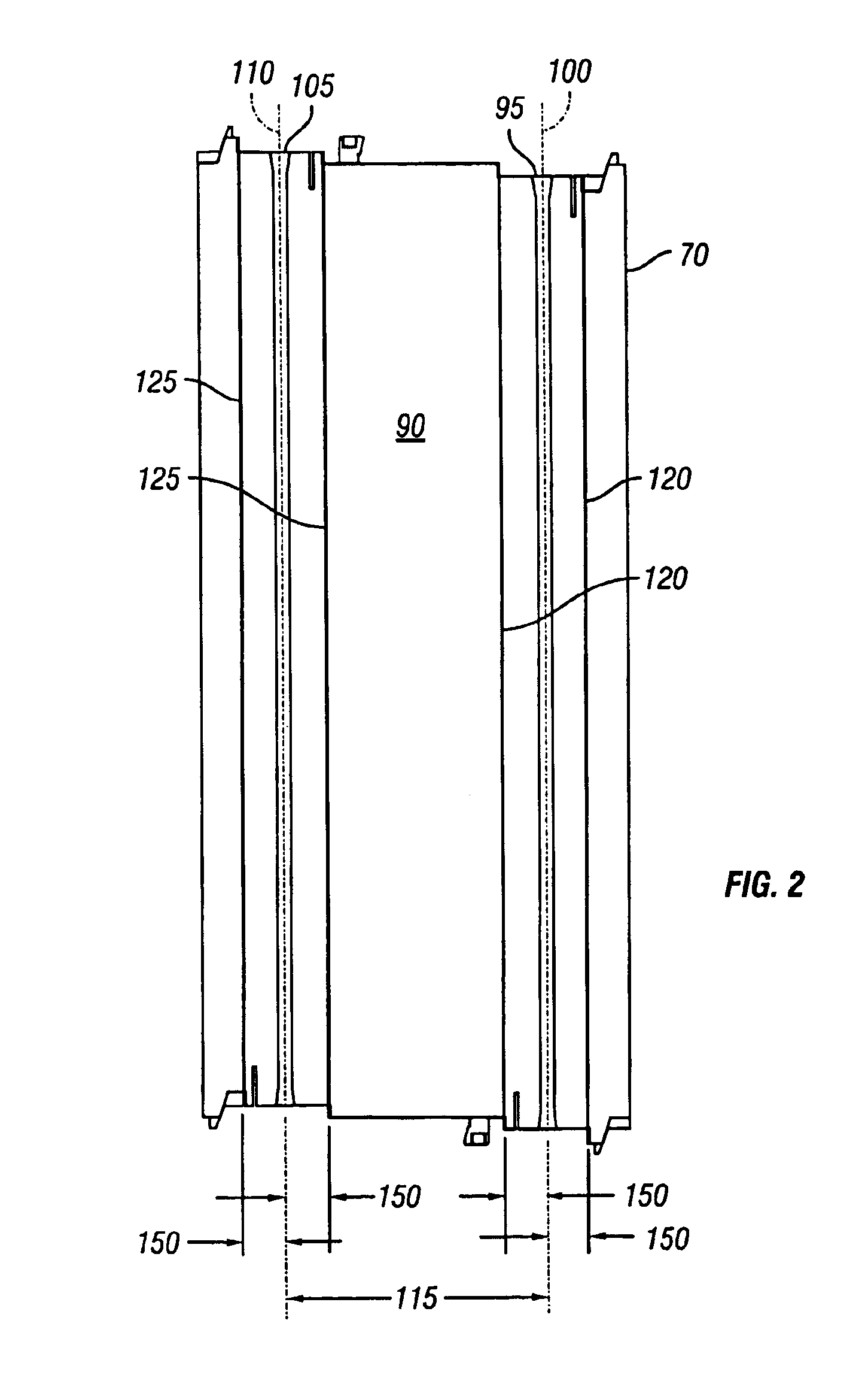
[0015]Referring to the figures, wherein like numerals are used to indicate like elements throughout, there is shown in FIGS. 1-4, a preferred embodiment of a toy vehicle slot track, generally designated 10, in accordance with the present invention.

[0016]Referring now to FIG. 1, the toy vehicle slot track 10 is shown assembled in a generally oval-shaped configuration. Also illustrated are a first toy vehicle 20 and a second toy vehicle 25. Each toy vehicle 20 and 25 has a maximum width 30 a...


PUM


Abstract

A toy vehicle slot track is disclosed with at least a pair of toy racing vehicles and at least a pair of guide slots, each guide slot in turn having a pair of exposed power supply rails. The toy vehicles are guided about the track by guide pins affixed to the toy vehicles, the guide pins running within the guide slots. In a first portion of the track, the guide slots are spaced apart at a distance greater than the maximum width of the toy vehicles. In a second portion of the track, the guide slots are spaced apart at a distance less than the maximum width of the toy vehicles. The power supply rails run parallel to and at a uniform spacing from the guide slots in both portions of the track, providing power in both track portions to electric motors contained in the toy vehicles.

Description

CROSS-REFERENCE TO RELATED APPLICATIONS[0001]This application claims benefit of U.S. Provisional Patent Application No. 60 / 423,186, “Toy Vehicle Slot Track”, filed Nov. 1, 2002.BACKGROUND OF THE INVENTION[0002]The present invention relates to a toy vehicle slot track, and more particularly to a toy vehicle slot track having a first portion wherein guide slots disposed in an upper surface of the track are spaced apart at a first distance and a second portion wherein the guide slots are spaced apart at a second distance.[0003]A variety of toy vehicle slot track constructions are known. Generally, the track construction comprises track segments having one or more guide slots for engaging a projecting pin on a toy vehicle which guide the toy vehicle around the track. The toy vehicles are typically powered through a pair of conductors embedded in the track.[0004]Prior art track constructions have presented various configurations of the guide slots. For example, multiple guide slots which...

Claims


Application Information

Patent Timeline
Patent Type & Authority Patents(United States)
IPC IPC(8): A63H18/02A63H18/00A63H18/12
CPCA63H18/12A63H18/02E01B1/00
Inventor D'ANGELO, JR., VINCENT J.DICKINSON, JAMES M.HUY, GERHART P.REISHER, DEAN C.
Owner MATTEL INC
Why Eureka
Try Eureka