Needle protection device

a protection device and needle technology, applied in the field of needle protection devices, can solve the problems of potential contact risk with needles, and no needle protection device that addresses the problems faced

Inactive Publication Date: 2005-04-26
NORFOLK MEDICAL
View PDF19 Cites 32 Cited by
  • Summary
  • Abstract
  • Description
  • Claims
  • Application Information

AI Technical Summary

Benefits of technology

[0006]The shield is mounted onto a clear plastic base, which is located on a needle or syringe, and remains in a “relaxed” position until the device comes into contact with the patient's skin. When the needle is inserted into a patient, the shield attaches to the patient's skin through an adhesive component. As the needle is withdrawn, the adhesive component pulls the shield out of its “relaxed” position. The adhesive component holds the center portion of the shield to the patient's skin, placing the shield in tension as the needle is withdrawn from the patient. The tensile force created by the withdrawal of the needle is greater than the spring force effect of the shield, thereby forcing the spiral type cut shield to extend into a protective cone along the length of the needle. When the needle is fully withdrawn, the shield is a fully protective cone around the needle and needle tip. The adhesive component then releases from the patient's skin, retracting the center most portion of the shield to a cone-like shape around the needle. The needle tip prevents the shield from returning to its “relaxed” position by becoming fixed in the center most portion of the shield, thereby forcing the shield to remain as a protective cone along the entire length of the needle.

Problems solved by technology

Although currently there exist various needle protection devices, most require the user to take an affirmative step thereby causing potential risk of contact with the needle.
Currently, there are not any needle protection devices that address the issues faced by subcutaneous needles.

Method used


Image

  • Needle protection device
  • Needle protection device
  • Needle protection device

Examples


Embodiment Construction

[0019]For the purpose of promoting an understanding of the principles of the invention, reference will be made to the embodiments illustrated in the drawings. It will, nevertheless, be understood that no limitation of the scope of the invention is thereby intended, such alterations and further modifications in the illustrated device and such further applications of the principles of the invention illustrated herein being contemplated as would normally occur to one skilled in the art to which the invention relates.

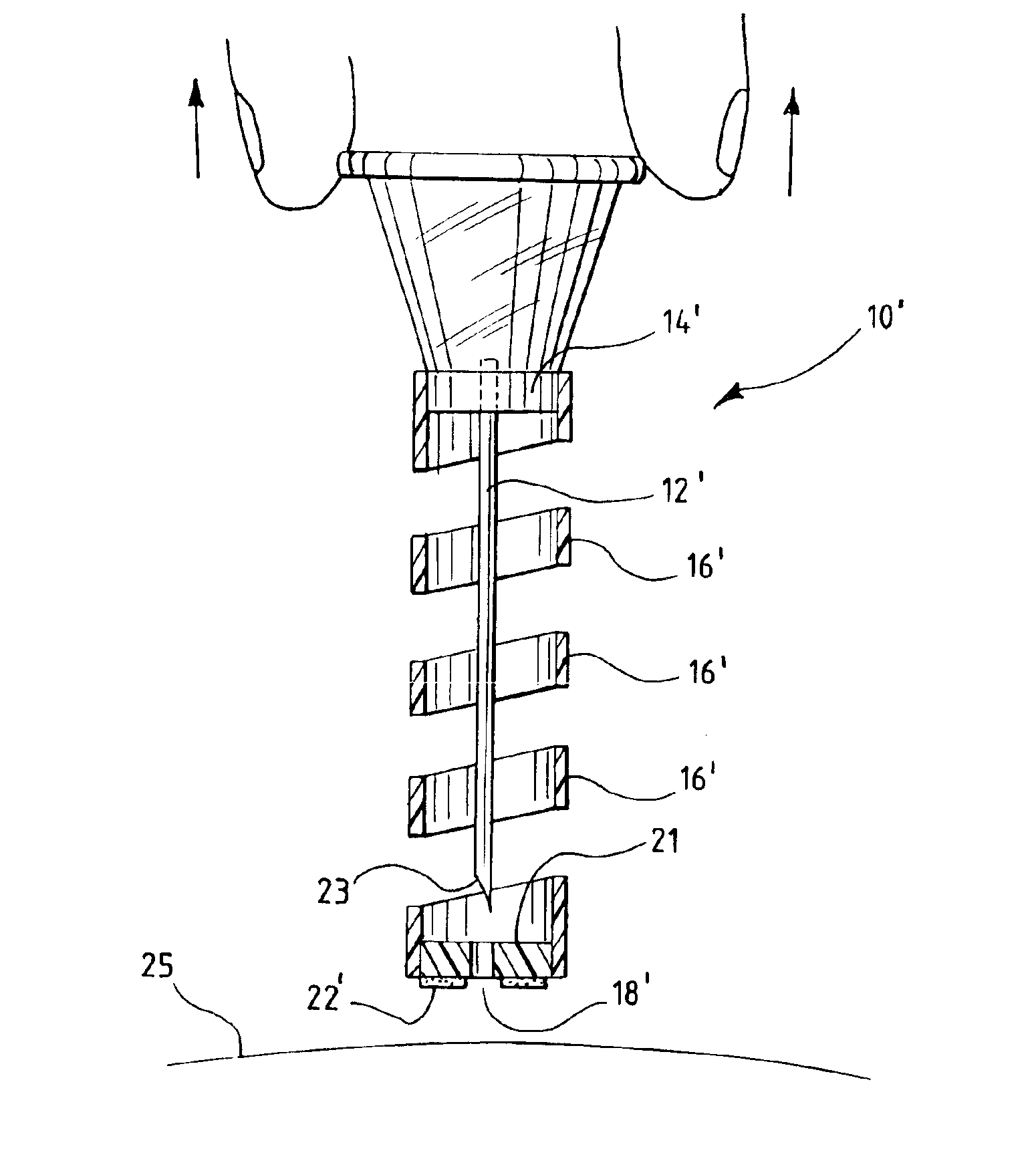
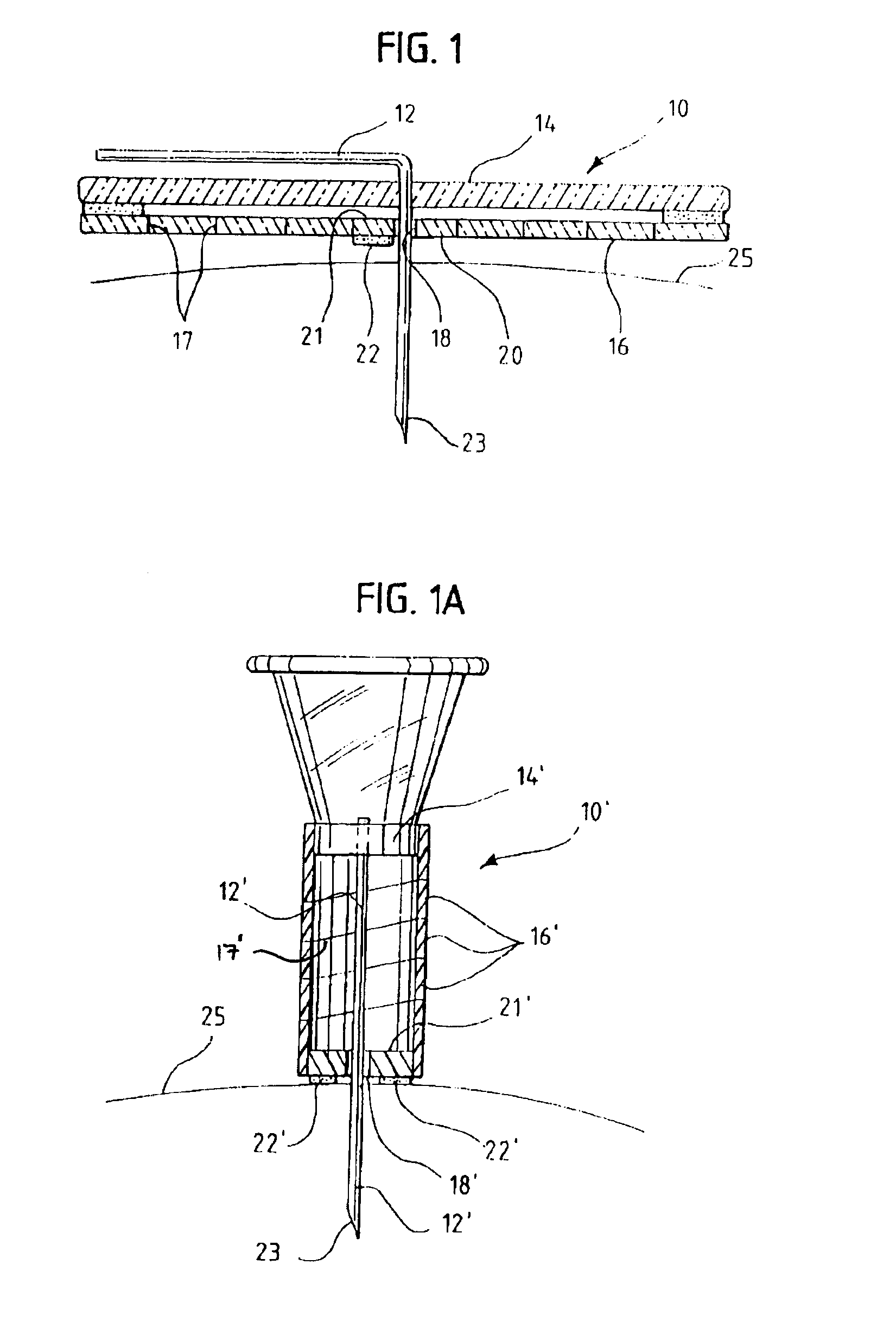
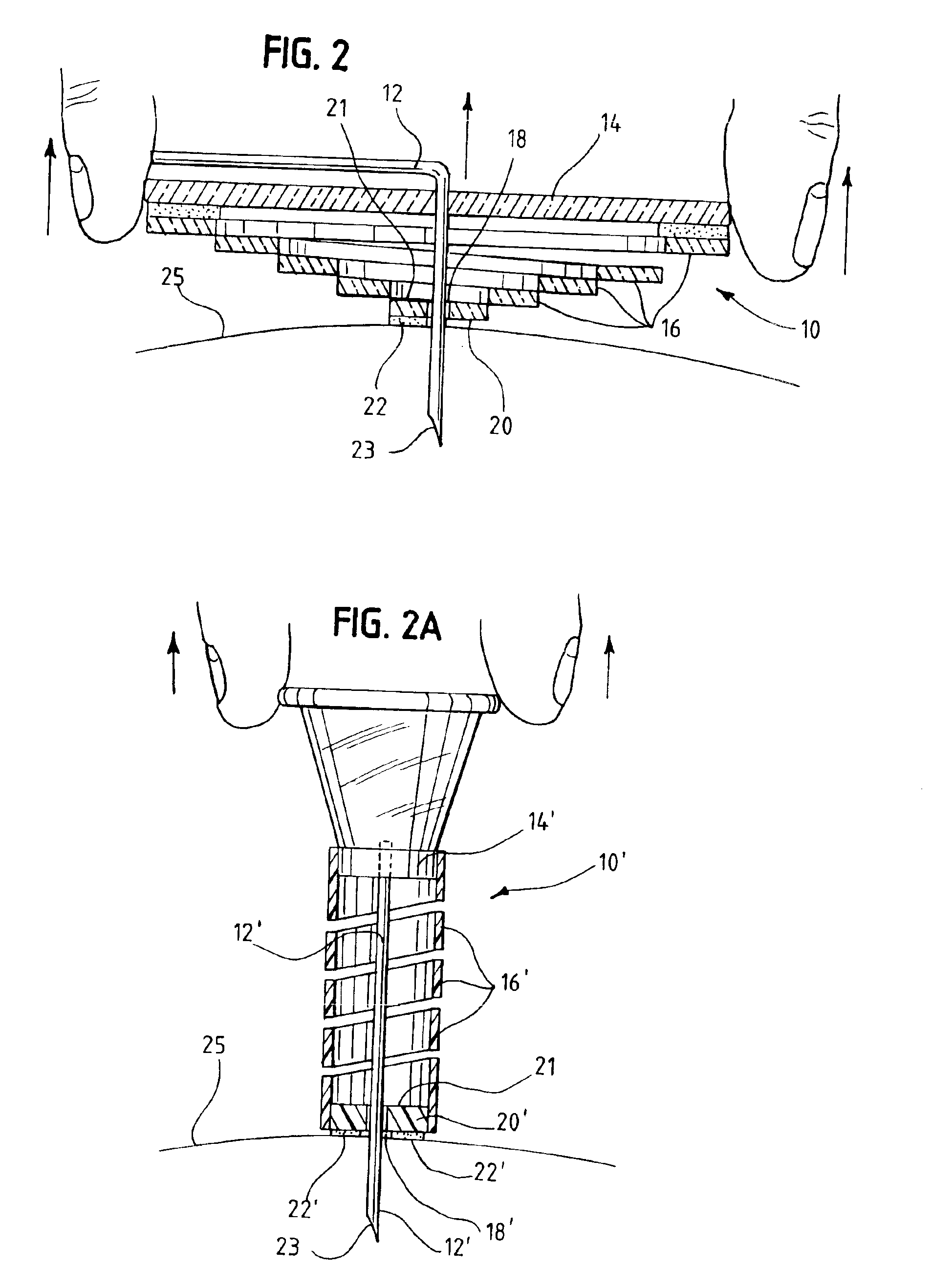
[0020]The needle safety and protection device 10 and 10′ is attached to a conventional medical needle 12 and 12′, and comprises a base 14 and 14′, and a shield 16 and 16′, as shown in FIGS. 1 and 1A. The base 14 and 14′ is made of a semi-rigid polymeric material and is mounted on the needle 12 and 12′ or on a support for the needle, at a distance sufficient to allow the needle 12 and 12′ to enter human skin and perform its function appropriately.

[0021]Shield 16 and 16′ is a...


PUM


Abstract

A needle safety and protection device that automatically caps the used tip of a needle the instant the needle is withdrawn from the patient to protect the user against infection risks. A spiral type cut safety shield remains relaxed until the device comes in contact with the patient's skin. The safety shield attaches to the patent's skin through an adhesive component creating a tensile force once the needle is withdrawn, extending the safety disk out of its relaxed position. Under tension, the safety disk creates a cone around the needle, forming a protective shield for the needle, without any assistance by the user. The tip of the needle then engages a portion of the shield, which prevents the tip from being re-inserted into the skin of the patient or the user of the needle.

Description

BACKGROUND OF THE INVENTION[0001]The present invention is an improved device for protecting users from needle sticks by automatically capping the used needle the instant the needle is withdrawn from the patient to protect the user against infection risks.DESCRIPTION OF RELATED ART[0002]Needles are used in the medical industry to deliver medications or to draw blood for diagnosis. United States health authorities estimate that some 600,000 to 800,000 accidental needle stick injuries occur every year. There are roughly 8,000,000 healthcare workers in the United States who are at risk of being stuck with a needle that is contaminated with AIDS, Hepatitis, Herpes, Tuberculosis, Fungi and a full range of infectious microorganisms.[0003]The purpose of this invention is to address the problem of transmission of diseases as a result of user contact with used needles. Although currently there exist various needle protection devices, most require the user to take an affirmative step thereby c...

Claims


Application Information

Patent Timeline
Patent Type & Authority Patents(United States)
IPC IPC(8): A61M5/158A61M5/14A61M5/32
CPCA61M5/158A61M5/326A61M2005/3267A61M2005/3249A61M2005/1581
Inventor DALTON, MICHAEL J.
Owner NORFOLK MEDICAL
Why Eureka
Try Eureka