
Puncture device causing less pain

A rod head and tail rod technology, applied in the field of puncture tools for micro blood sample collection, can solve problems such as large infection, increase product production cost, and cumbersome removal, so as to reduce the risk of infection, improve work efficiency, and simplify molds effect of structure

Active Publication Date: 2014-05-07
HUAIAN EFAST INNOVATION TECH CO LTD
View PDF15 Cites 14 Cited by
  • Summary
  • Abstract
  • Description
  • Claims
  • Application Information

AI Technical Summary

Problems solved by technology

After completing a puncture blood sample collection, the blood collection needle must be removed from the puncture device. There are two methods: one is to remove it manually directly, and the operator holds the blood collection needle that has completed the puncture operation with his fingers and forcibly pulls it out of the holder. The operation method is cumbersome, and the operator is easy to touch the needle tip and blood at the front end of the blood collection needle, which has psychological pressure and a greater risk of infection; the second is to use the forced ejection device installed on the puncture device to remove, the forced ejection device is generally It is a push rod or collar attached to the outside of the puncture device, and a component that is connected with the push rod or collar and extends to the bottom of the blood collection needle holder. Removal is cumbersome, and the sequence is: remove the cover (rotate or pull) - operate the push rod or collar to move forward to force the blood collection needle out - manually return the push rod or collar
During use, the operator needs to install or disassemble the blood collection needle compartment cover multiple times to complete the needle withdrawal operation, which is cumbersome and inefficient.
[0008] The puncture device has the action of rotating the indicator sleeve and pulling the tail rod in use, which needs to increase the friction between the parts and the operator's hand. The existing structure is to set a concave part or a convex ring on the operating part, but the mold of this structure Complicated, which increases the production cost of the product

Method used


Image

  • Puncture device causing less pain
  • Puncture device causing less pain
  • Puncture device causing less pain

Examples


specific Embodiment approach

[0041]The above summary of the present invention is not intended to present each embodiment or every aspect of the present invention. Additional features and advantages of the present invention will be apparent from the detailed description and drawings set forth below.

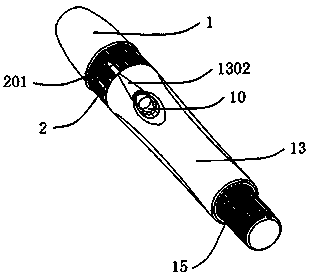
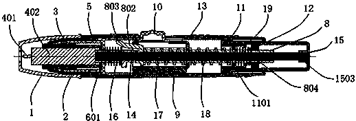
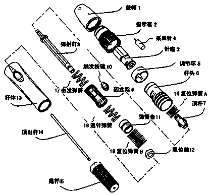
[0042] to combine Figure 1~Figure 14 As shown, the present invention comprises blood collection needle 4, rod head 6, rod body 13 and tail rod 15, and described rod head 6 is fixed on the front end of rod body 13, and tail rod 15 is arranged at the rear end of rod body 13, is provided with ejection Assembly; the ejection assembly includes an ejection rod 8, which is movably connected to a fixed frame 9, and the fixed frame 9 is fixed on the inner wall of the rod body 13, and the ejection rod 8 is respectively sleeved with firing springs 17 from front to rear , return spring B19, and the spring limit hoops located at both ends of the ejection rod 8, the needle holder 3 is movably connected in the rod head 6,...


PUM


Abstract

The invention discloses a puncture device causing less pain. The puncture device comprises a blood taking needle, a rod head, a rod body and a tail rod, wherein the rod head is fixed to the front end of the rod body; the tail rod is arranged at the back end of the rod body; an ejection assembly is arranged in the rod body; a needle seat is movably connected in the rod head; a handle rod of the blood taking needle is connected in the needle seat; the front end of an ejection rod in the ejection assembly is over against a carrier rod communicated with the back end of the needle seat. In the puncture device causing less pain having the structure, the ejection device is separated from the needle seat of the blood taking needle, thereby interrupting deviation shake caused by ejection of the ejection device in the transmission process of the needle seat, preventing the phenomenon of shake or deviation of the blood taking needle in a skin contact process, and reducing pain of a patient. Moreover, by improving an indicating sleeve and the tail rod, the infection risk of an operator is further lowered, the operation efficiency is increased, and the manufacturing cost is reduced.

Description

technical field [0001] The invention relates to the technical field of medical diagnostic instruments, in particular to a puncture tool for collecting a small amount of blood samples that can reduce the pain of a specific patient. Background technique [0002] Quantitative determination of relevant components in human body fluids is very common in modern medicine. For example, for a specific patient, glucose, lactate, cholesterol and bilirubin in blood need to be monitored and analyzed. Early operators used an independent blood collection needle to manually puncture the patient's skin to form a wound to collect blood samples. This method has high technical requirements and certain psychological pressure for the operator and certain patients, and the patient feels great pain. [0003] U.S. Patent No. 4,503,856 on March 12, 1985 discloses a piercing device having a tubular housing, a lancet holder slidable in the housing, and a compressible spring to provide the holder Force ...

Claims


Application Information

Patent Timeline
IPC IPC(8): A61B5/15
Inventor 项文项明亮
Owner HUAIAN EFAST INNOVATION TECH CO LTD
Learn More