This helps you quickly interpret patents by identifying the three key elements:
Problems solved by technology
Method used
Benefits of technology
[0014]The preferred embodiment of the surgical fastener of the present invention is formed into the configuration of a continuous helical coil. The continuous helical coil is longitudinally collapsible and expandable. At the distal end of the helical fastener is a point for enhancing penetration into tissue. The proximal end of the helical fastener has a T-bar which sections the diameter of the fastener, thereby providing a surface for receiving and transmitting longitudinal and rotational forces so that the fastener may be driven into tissue by a corkscrew action. The pitch and length of the helical fastener may vary upon the application as can its diameter and configuration of the most proximal and distal coils comprising the fastener. Additionally, the material selection and fastener stiffness may be selected wi
Problems solved by technology
Since conventional staples require deformation and must cooperate with applicators having an anvil or other means to deform the staples, conventional applicators typically comprise complex structures and can be prohibitively expensive.
It is to be appreciated, therefore, that the fastener applicators have become complex and expensive instruments.
The two piece fasteners cannot be unlocked and are not removable.
Thus, as with the other conventional applications, two piece fasteners are limited since they cannot be used where access to tissue is from one direction only.
As mentioned previously, how
Method used
Image
Click on the blue label to locate the original text in one second.
Reading with bidirectional positioning of images and text.
Examples
Embodiment Construction
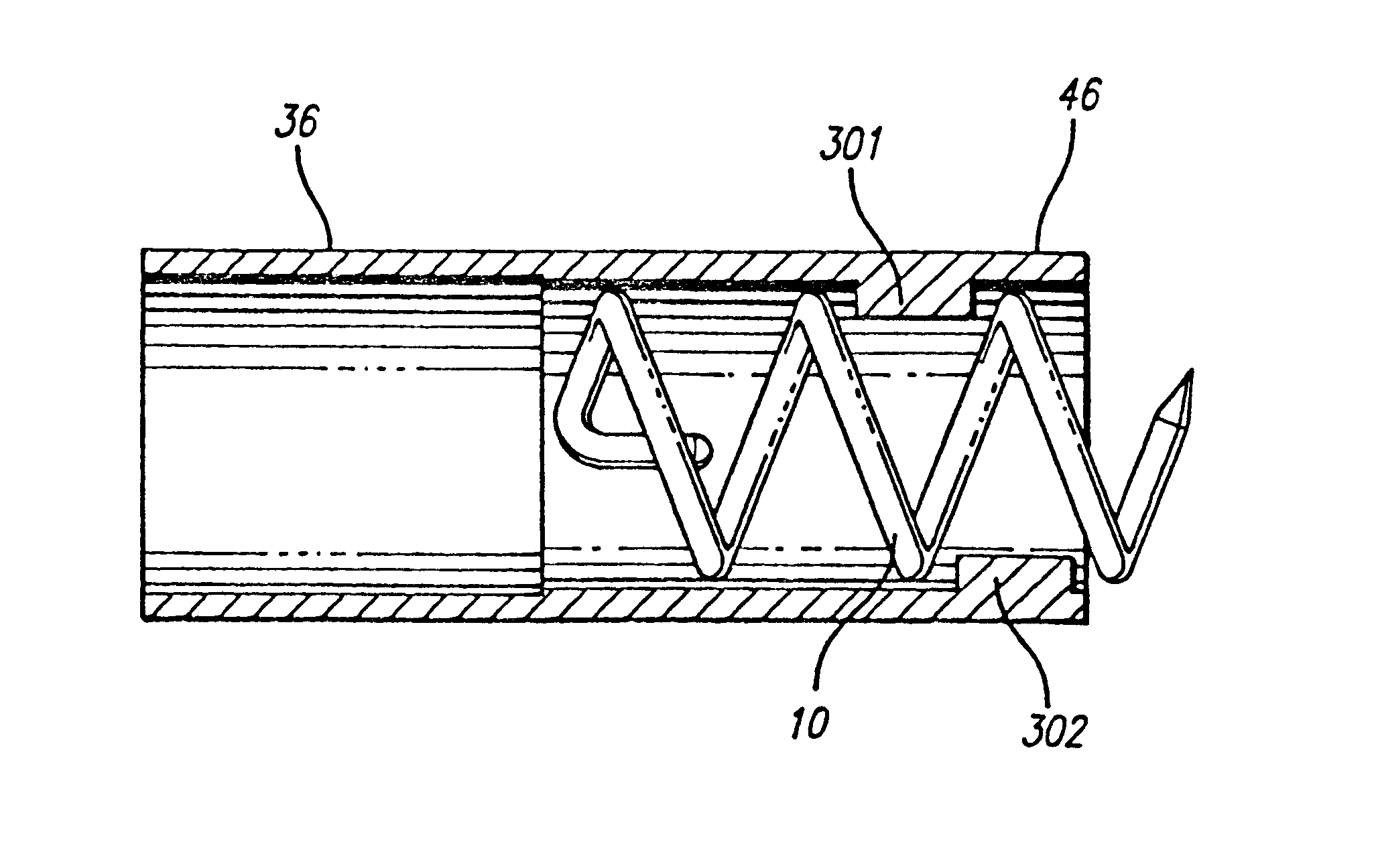
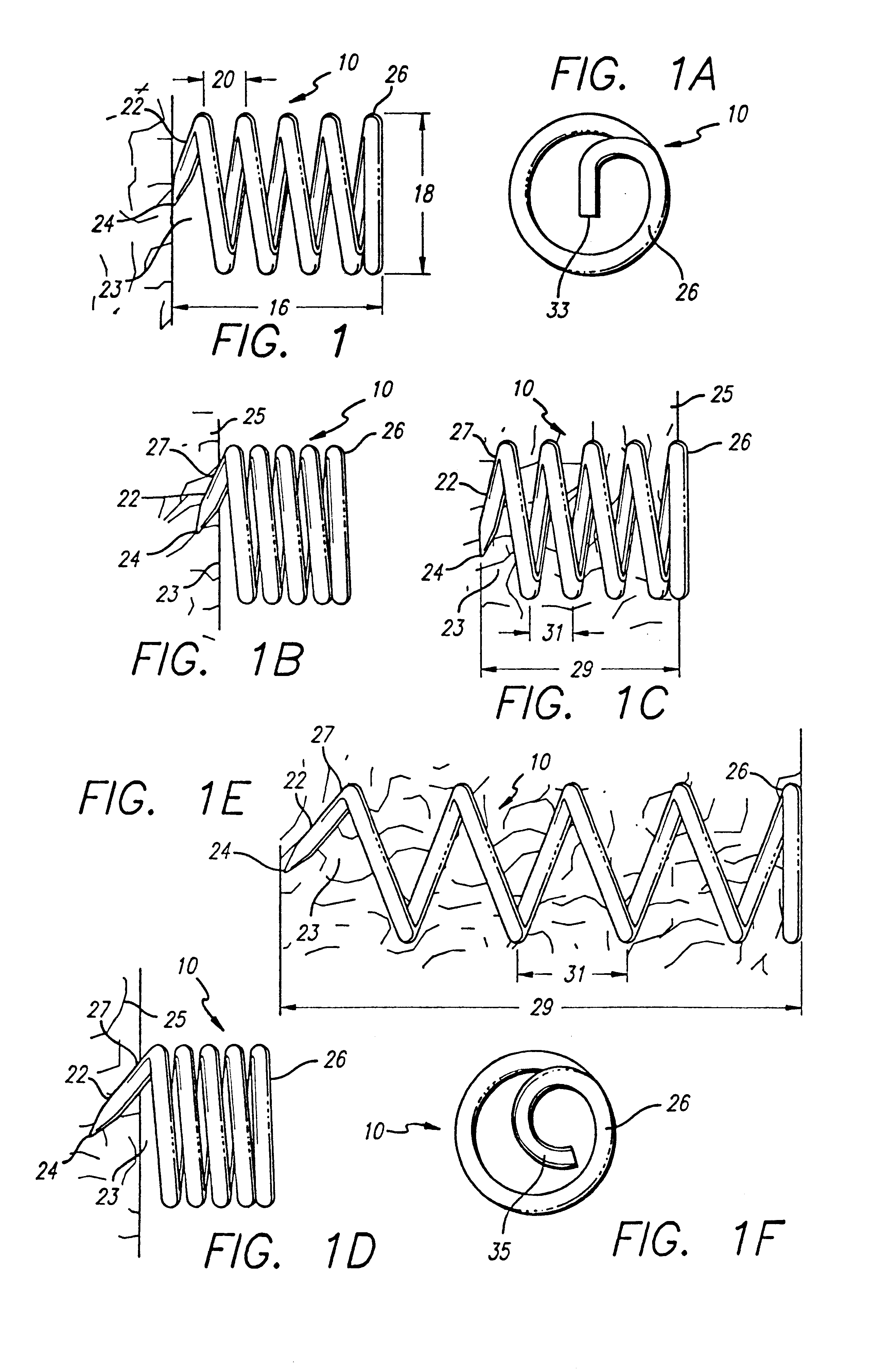
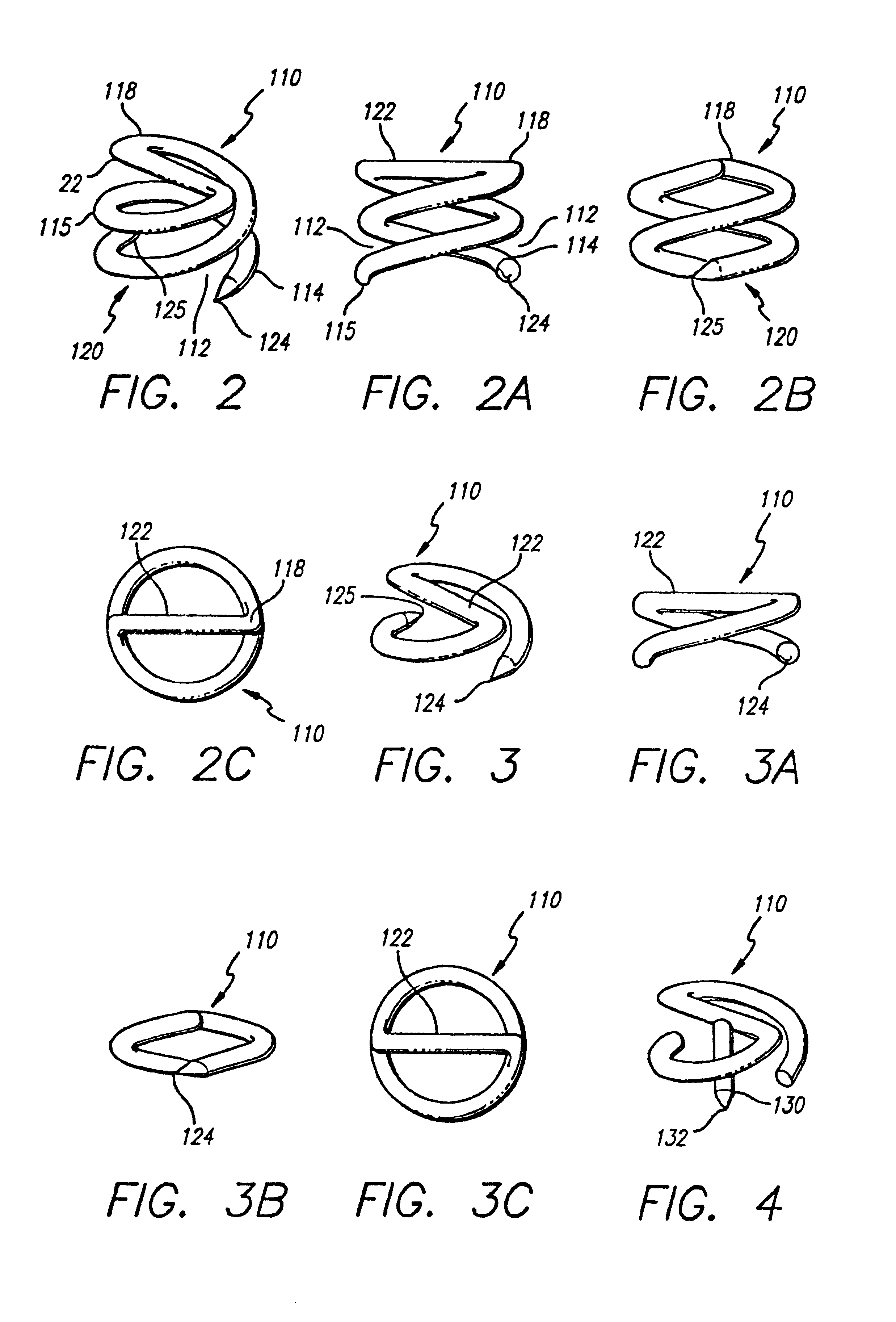
[0060]As is shown in the drawings, which are included for purposes of illustration and not by way of limitation, the invention is embodied in a continuous helical fastener and an applicator therefor. The helical fastener has a high retentive surface area and the applicator has a simple design and functions to dispense the helical fasteners, without substantially deforming the fasteners, into body tissue, access to which is from one direction only. Some conventional fasteners require deformation to hold tissue and are consequently limited since they require complex applicators to attach them into tissue. Other conventional fasteners lack high retentive surface area for securely holding tissue. Still other fastener / applicator systems require access to tissue from two directions in order to accomplish attaching a fastener to tissue. Thus, the helical fastener and applicator of the present invention provides a superior means to attach fasteners to tissue.
[0061]One embodiment of the pres...
PUM
Abstract
A helical fastener having a high retentive surface area is provided and has a first end for enhancing penetration into tissue and a second end comprising a coil sectioning a diameter of the fastener for receiving longitudinal and rotational forces. The helical fasteners are attached to body tissue by a fastener applicator having a proximal portion comprising a handle and an actuator and an elongate distal portion for housing a plurality of fasteners. A transferring action of the actuator provides longitudinal and rotational movement of the fasteners out of the distal portion and into body tissue.
Description
CROSS-REFERENCE TO RELATED APPLICATIONS[0001]The present application is a continuation of U.S. application Ser. No. 09 / 968,100, filed on Oct. 1, 2001, now U.S. Pat. No. 6,562,051, which is a continuation of U.S. application Ser. No. 08 / 499,279, filed on Jul. 7, 1995, now U.S. Pat. No. 6,296,656, which is a divisional of U.S. application Ser. No. 08 / 286,878, filed on Aug. 5, 1994, now U.S. Pat. No. 5,582,616. The priority of these prior applications is expressly claimed and their disclosures are hereby incorporated by reference in their entirety.BACKGROUND OF THE INVENTION[0002]This invention relates to surgical fasteners and their associated applicators, and more particularly, surgically fastening material to tissue.[0003]Fasteners have been used surgically to eliminate the need for suturing, which is both time consuming and inconvenient. In many applications the surgeon can use a stapler apparatus, i.e., a fastener implanting device loaded with surgical fasteners to accomplish in a...
Claims
Application Information
Patent Timeline
Application Date:The date an application was filed.
Publication Date:The date a patent or application was officially published.
First Publication Date:The earliest publication date of a patent with the same application number.
Issue Date:Publication date of the patent grant document.
PCT Entry Date:The Entry date of PCT National Phase.
Estimated Expiry Date:The statutory expiry date of a patent right according to the Patent Law, and it is the longest term of protection that the patent right can achieve without the termination of the patent right due to other reasons(Term extension factor has been taken into account ).
Invalid Date:Actual expiry date is based on effective date or publication date of legal transaction data of invalid patent.