
Control system and method for electric vehicle

a control system and electric vehicle technology, applied in the field of electric vehicles, can solve problems such as single point of failure of the traction system

Inactive Publication Date: 2005-04-26
OSHKOSH CORPORATION
View PDF179 Cites 345 Cited by
  • Summary
  • Abstract
  • Description
  • Claims
  • Application Information

AI Technical Summary

Benefits of technology

[0006]According to a first preferred embodiment, an electric traction vehicle comprises a vehicle platform, a communication network, a power source mounted on the vehicle platform, a plurality of drive wheels rotatably mounted on the vehicle platform, a plurality of electric motors coupled to ...

Problems solved by technology

It also provide a single point of failure for the traction system.

Method used


Image

  • Control system and method for electric vehicle
  • Control system and method for electric vehicle
  • Control system and method for electric vehicle

Examples


Embodiment Construction

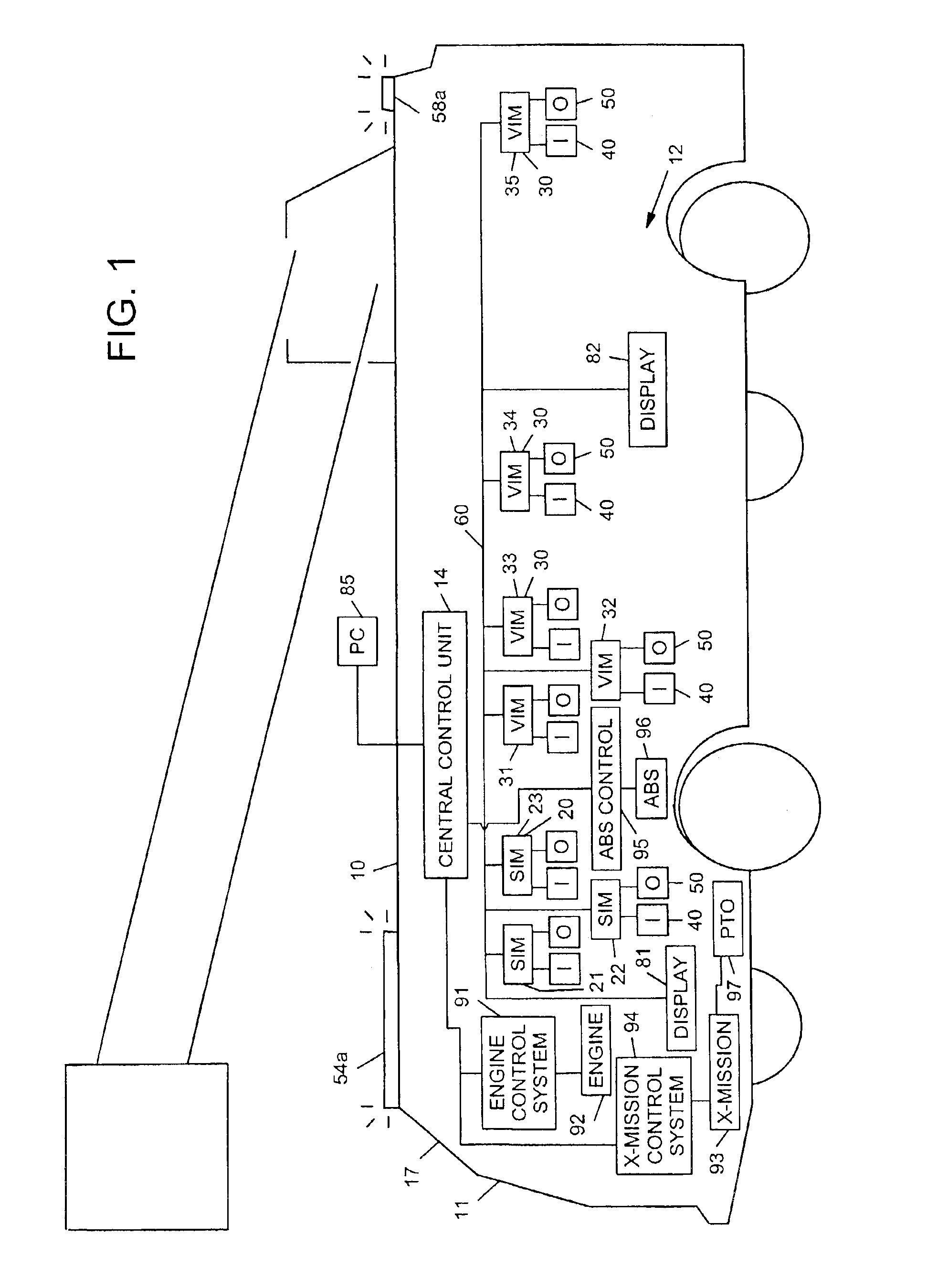
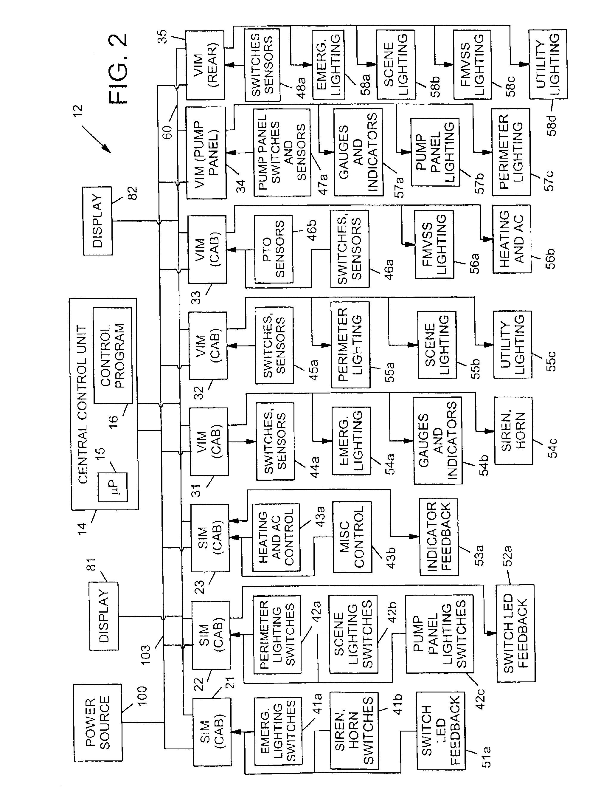
[0064]patent application Ser. No. 09 / 384,393, filed Aug. 27, 1999, allowed, discloses various embodiments of a control system architecture in connection with fire trucks, military vehicles and other types of vehicles. A particularly advantageous use of the preferred control system architecture is in the context of electric traction vehicles and, as described below, the vehicles disclosed in these applications may be implemented as electric traction vehicles. For such uses, the control systems described in the above-mentioned applications may be used to control additional output devices associated with the electric traction vehicle such as electric motors used to drive motion of the vehicle, and to provide I / O status information which may be transmitted off-board the vehicle. For convenience, the contents of the above-mentioned application is repeated below, followed by a description of an electric traction vehicle embodiment and remote monitoring applications which in a preferred em...


PUM

PropertyMeasurementUnit
Poweraaaaaaaaaa
Poweraaaaaaaaaa
Poweraaaaaaaaaa

Abstract

An electric traction vehicle comprises a vehicle platform, a communication network, a power source mounted on the vehicle platform, a plurality of drive wheels rotatably mounted on the vehicle platform, a plurality of electric motors coupled to respective ones of the plurality of drive wheels, and a plurality of microprocessor-based interface modules coupled to the plurality of electric motors. The interface modules are configured to control the plurality of electric motors and are coupled to each other by way of the communication network.

Description

CROSS-REFERENCE TO RELATED APPLICATIONS[0001]This application is a continuation-in-part of U.S. Ser. No. 09 / 927,946, filed Aug. 10, 2001, entitled “Military Vehicle Having Cooperative Control Network With Distributed I / O Interfacing,” pending, which is a continuation-in-part of U.S. Ser. No. 09 / 384,393, filed Aug. 27, 1999, entitled “Military Vehicle Having Cooperative Control Network With Distributed I / O Interfacing,” now U.S. Pat. No. 6,421,593, which is a continuation-in-part of U.S. Ser. No. 09 / 364,690, filed Jul. 30, 1999, entitled “Firefighting Vehicle Having Cooperative Control Network With Distributed I / O Interfacing,” abandoned, each of which is hereby expressly incorporated by reference. This application is also a continuation-in-part of U.S. Ser. No. 09 / 500,506, filed Feb. 9, 2000, entitled “Equipment Service Vehicle Having On-Board Diagnostic System,” allowed now U.S. Pat. No. 6,553,290, also expressly incorporated by reference. This application is also a continuation-in...

Claims


Application Information

Patent Timeline
IPC IPC(8): A62C27/00B60L3/12B60L11/12B60L15/06B60L11/18B60L11/02B60L15/00B60R16/02B65F3/02B65F3/04G01M17/00G07C5/00G07C5/08G08G1/123B60L50/15B60R16/03
CPCA62C27/00B60L1/003B60L3/12B60L11/123B60L11/1887B60L11/1892B60L11/1894B60L15/06B60R16/0315B65F3/043B65F3/045G01M17/00G07C5/008G07C5/08G07C5/085G08G1/20B28C5/4206B60L2200/26B60L2200/36B60L2220/12B60L2220/14B60L2240/423B60L2240/70B60L2250/10B60L2250/16Y02T10/6217Y02T10/644Y02T10/7077Y02T10/7291Y02T90/16Y02T90/34Y02W30/10B60L50/61B60L58/40B60L58/33B60L58/34Y02T10/62Y02T10/64Y02T10/72Y02T90/40Y02T10/70Y02T10/7072
Inventor YAKES, CHRISTOPHER K.MORROW, JON J.PILLAR, DUANE R.SQUIRES, BRADLEY C.
Owner OSHKOSH CORPORATION
Learn More