
Disassembling object code

a technology of object code and disassembly, applied in the direction of program code transformation, program control, specific program execution arrangement, etc., can solve the problems of not being able to optimize, not being able to read, and being extremely difficult, if not impossible, for a human operator to read

Inactive Publication Date: 2005-04-26
STMICROELECTRONICS LTD
View PDF10 Cites 15 Cited by
  • Summary
  • Abstract
  • Description
  • Claims
  • Application Information

AI Technical Summary

Benefits of technology

The present invention provides a method and a lister for generating a source code listing from an object code sequence that includes a plurality of program instructions. The method involves identifying relocation instructions in the section data and using them to modify the object code sequence to generate an executable program. The relocation instructions can be associated with a specific location in the section data or can be embedded in the final executable program. The source code and additional information derived from the relocation instructions can be displayed in human-readable form. The technical effect of this invention is to improve the efficiency and accuracy of generating source code from object code sequences.

Problems solved by technology

This optimisation is not possible before linking as information from other program modules is often required.
The source code is useful as machine readable object code is represented simply as hexadecimal numbers and is therefore extremely difficult, if not impossible, for a human operator to read.
This is inconvenient during testing or debugging as if an error occurs it is not possible to determine if the value of the original variable was incorrect or if an error has occurred elsewhere.
Another problem with existing disassembly techniques is as follows.
Thus, it is not possible to assess whether or not an error has occurred in a directive itself rather than in the source code, or whether the disassembled source code is the same as the original source code which itself makes it more difficult to locate any incorrect code.

Method used


Image

  • Disassembling object code
  • Disassembling object code
  • Disassembling object code

Examples


Embodiment Construction

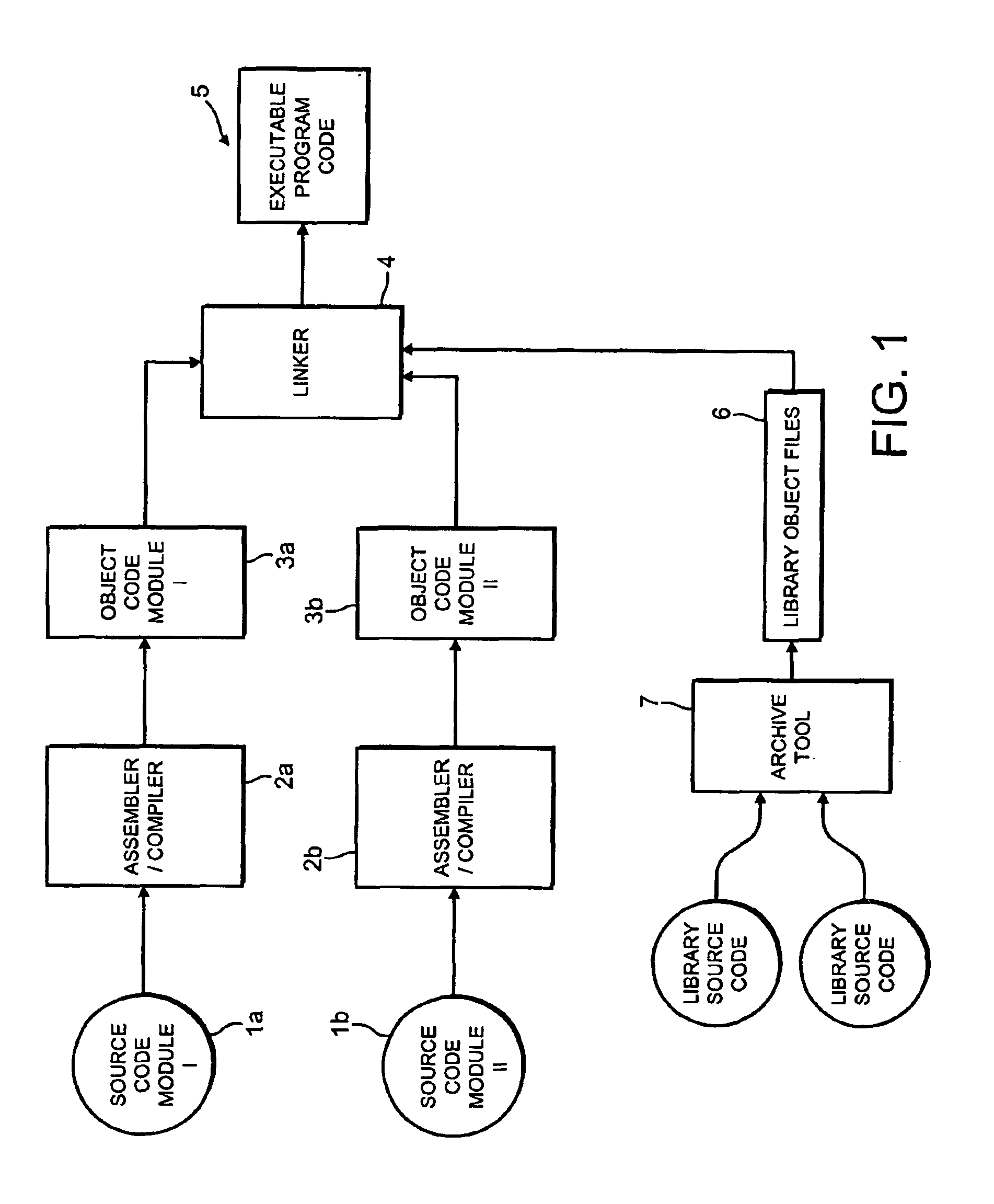
[0025]With reference to FIG. 1, a system for linking a number of program modules to form a single executable program is shown schematically. A number of program source code modules 1a,1b, each module written in a high level language is provided. The particular high level language used for each source code module may vary from module to module, or alternatively all of the program source code modules may be written in the same high level language. Each source code module 1a, 1b, is input to a respective assembler / compiler 2a,2b which assembles and / or compiles the high level language of the source code module to produce an object code module 3a,3b.

[0026]Each assembler generates an object code module including sets of section data. Each set of section data may have a set of relocations generated by the assembler to describe how the section data is to be patched so as to render it compatible with other section data to form the program 5. These relocations are generated by the assembler....


PUM


Abstract

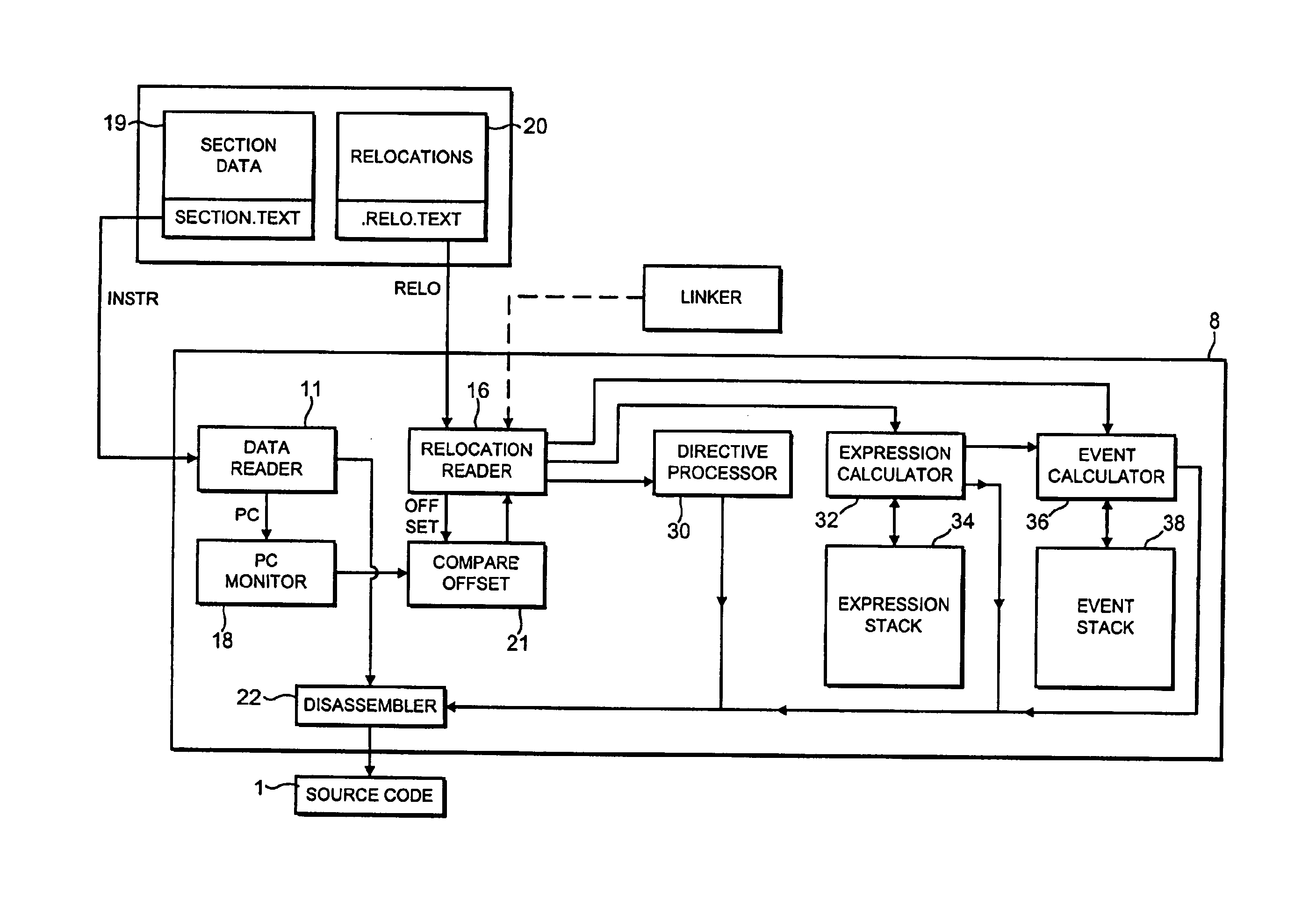
A method of disassembling object code to generate the original source code is discussed, together with a lister for performing the disassembly. The object code has relocation sections associated with some of the section data. For each location in the section data the lister determines if there is an associated relocation instruction and if there is, the lister derives certain additional information concerning the section data. The lister then generates the original source code, including the additional information.One example of the additional information is an arithmetic expression used to calculate a value in a relocation instruction. The set of relocations associated with the location of the instruction are read in turn by the lister and by using an expression calculator and an expression stack, the original arithmetic expression can be reconstructed.

Description

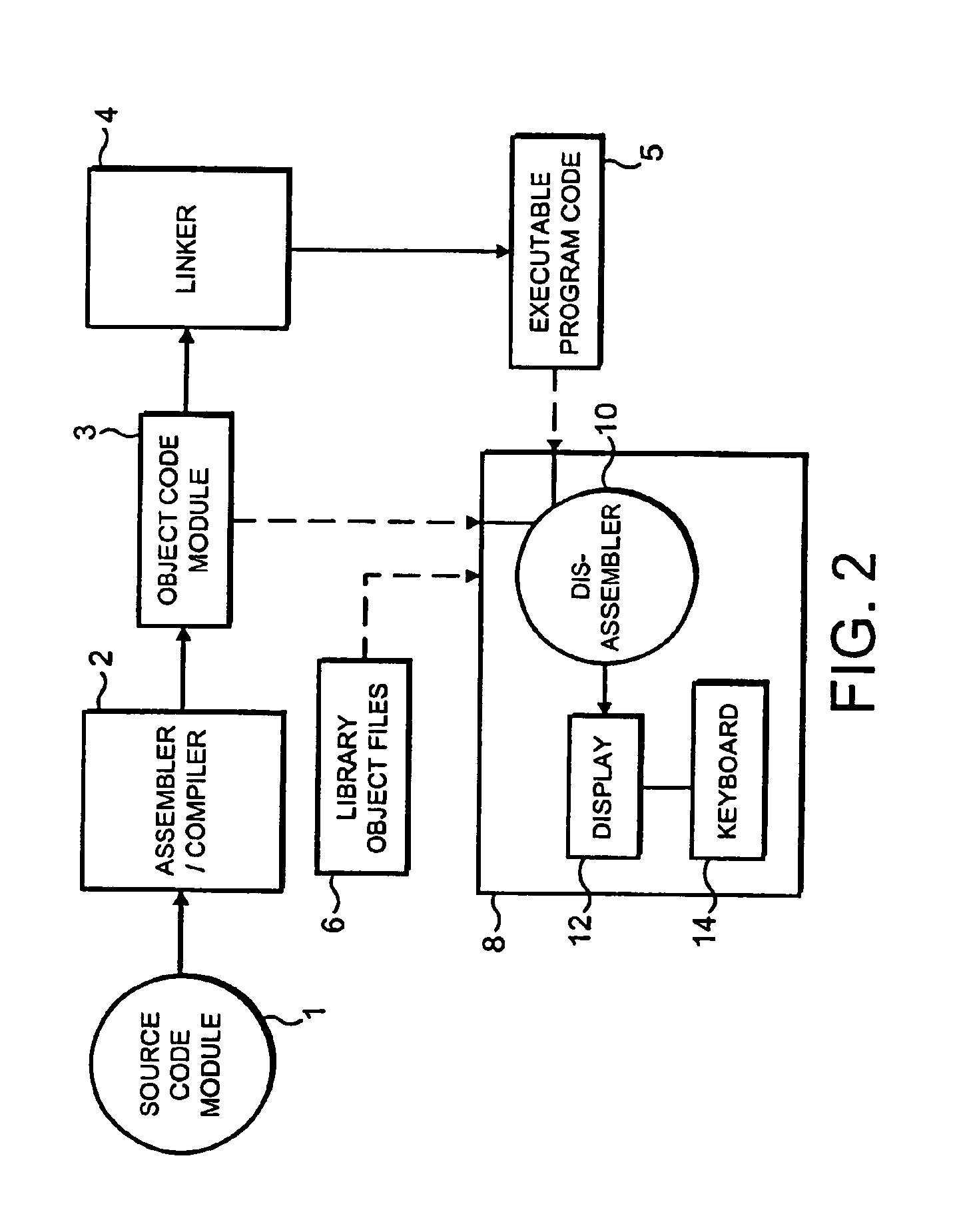
FIELD OF THE INVENTION[0001]The present invention relates to disassembling object code to generate the source code from which the object code was derived.BACKGROUND TO THE INVENTION[0002]It is known practice to develop large and complex computer programs by developing a number of small program modules which, for example, perform a single discrete function and subsequently joining all of these small program modules together to form the complete, single required program. This is advantageous as a number of modules may be developed in parallel and development and testing of the individual, smaller modules is considered to be much easier.[0003]The modules are generally written in source code which is normally a high level language which can be generated by a human and which is in a human readable form. An assembler / compiler reads each source code module and assembles and / or compiles the high level language of the source code module to produce an object code module. The assembler also ge...

Claims


Application Information

Patent Timeline
Patent Type & Authority Patents(United States)
IPC IPC(8): G06F9/44G06F9/445G06F9/45
CPCG06F8/54G06F8/53
Inventor MCCORMACK, MARIAN
Owner STMICROELECTRONICS LTD
Learn More