Loader coupler with adjustable dump and roll-back stops

a coupler and loader technology, applied in the direction of couplings, mechanical machines/dredgers, mechanical equipment, etc., can solve the problems of deficient fixed stops in many respects, stops may not be properly positioned for a different loader or other apparatus

Inactive Publication Date: 2005-05-03
JRB ATTACHMENTS
View PDF7 Cites 19 Cited by
  • Summary
  • Abstract
  • Description
  • Claims
  • Application Information

AI Technical Summary

Benefits of technology

[0008]Numerous benefits and advantages of the present invention will occur to those of ordinary skill in the art to which the invention pertains upon reading this specification.

Problems solved by technology

These stops are fixedly secured to the coupler body by welding and are not adjustable.
These prior, fixed stops are deficient in many respects.
First, due to manufacturing tolerances and tolerance build-up, oftentimes the stops do not engage the loader arms as desired.
Secondly, while the stops may perform perfectly on a first loader or other apparatus carrying the coupler, the stops may not be properly positioned for a different loader or other apparatus.

Method used


Image

  • Loader coupler with adjustable dump and roll-back stops
  • Loader coupler with adjustable dump and roll-back stops
  • Loader coupler with adjustable dump and roll-back stops

Examples


Embodiment Construction

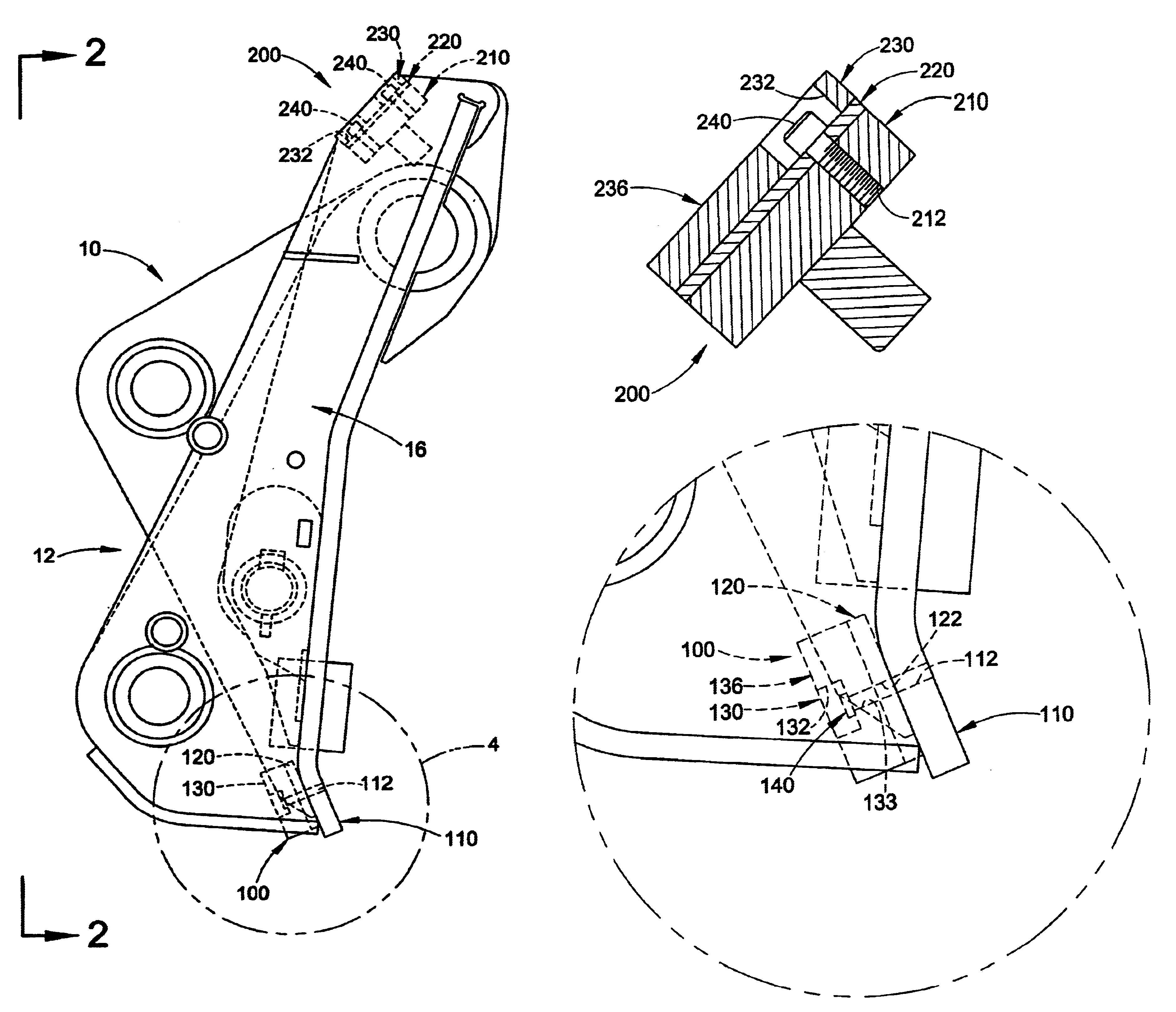
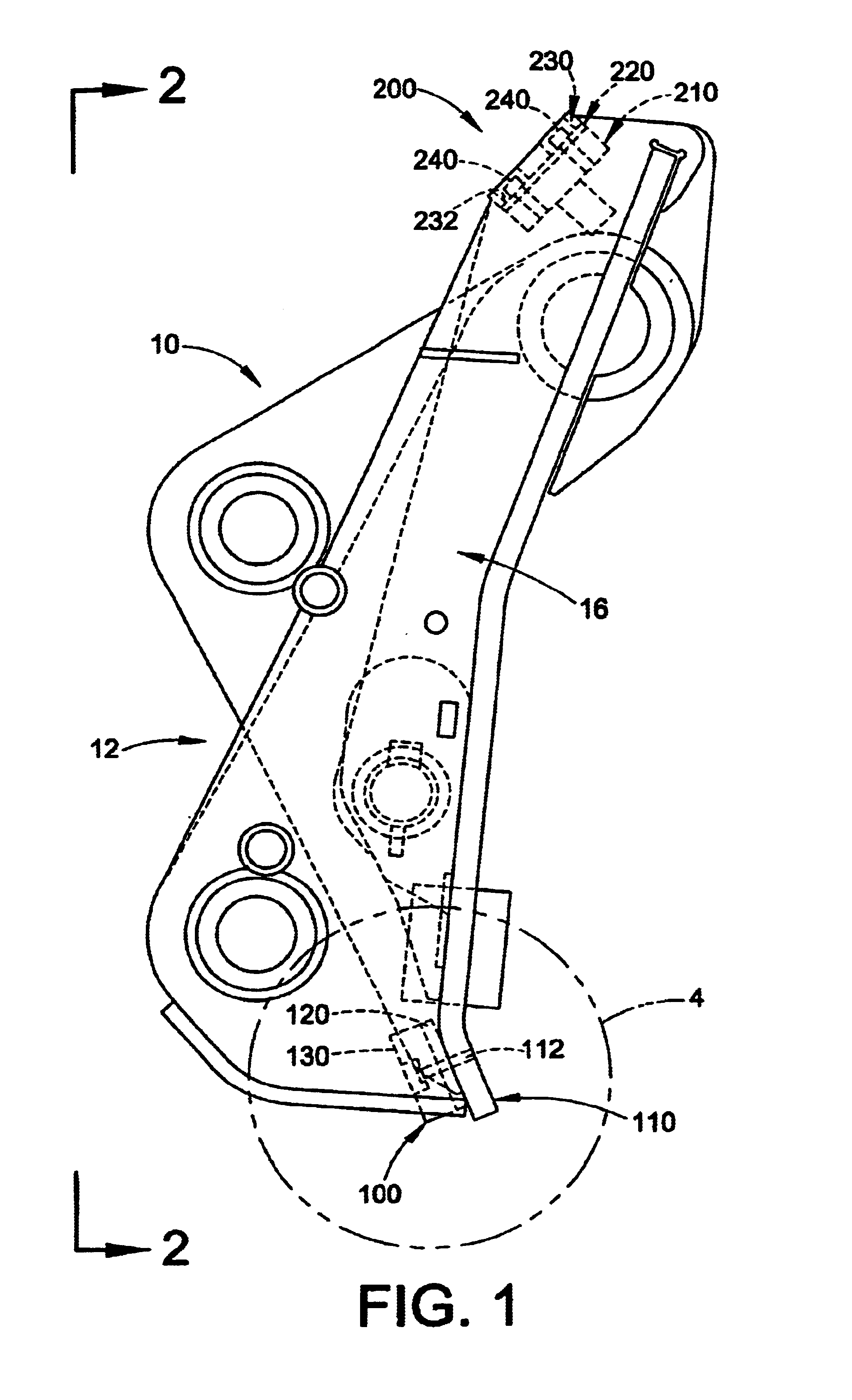
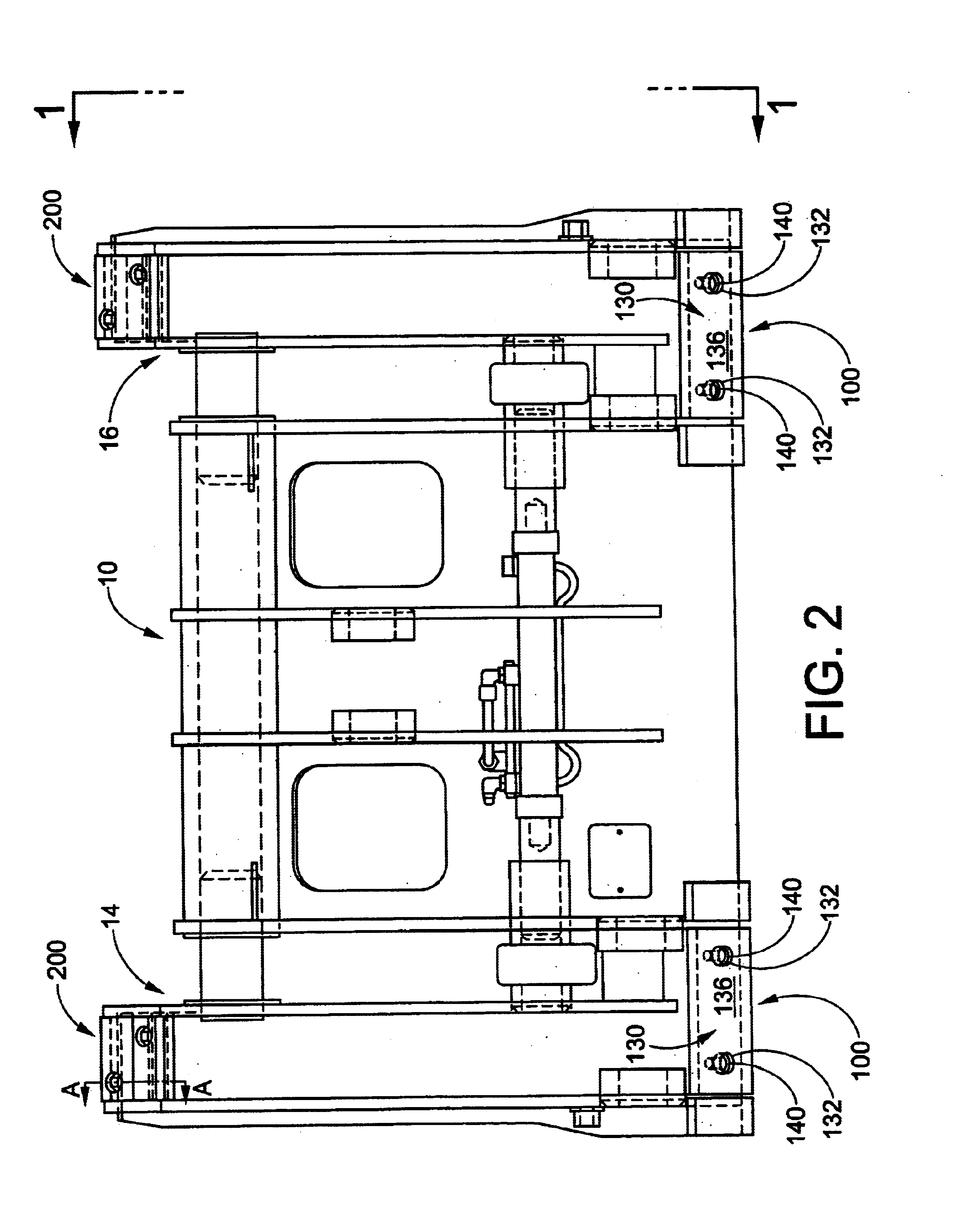
[0019]FIGS. 1 and 2 illustrate a loader coupler 10 that is conventional in all respects except that it is equipped with adjustable dump stops 100 and adjustable roll-back stops 200 formed in accordance with the present invention. The dump stops 100 are located on a rear face or portion 12 (the face oriented toward the loader or other associated machine carrying the coupler 10) of the coupler 10 on opposite lateral sides 14,16 thereof. Likewise, the roll-back stops 200 are located on a rear face of the coupler 10 on its opposite lateral sides. Those of ordinary skill in the art will recognize that the dump and roll-back stops are located in positions that correspond to the location of conventional dump and roll-back stops, respectively. For simplicity and ease of understanding the invention, only one dump stop 100 and one roll-back stop 200 (those located on the second lateral side 16 of the coupler 10) are described in detail below. Those of ordinary skill in the art will recognize ...


PUM


Abstract

A loader coupler includes first and second dump stops located on opposite lateral sides of the coupler and first and second roll-back stops located on opposite lateral sides of the coupler. Each of the dump and roll-back stops includes a base connected to or formed as a part of the coupler; at least one shim located adjacent the base; and, a cover releasably connected to the base and located adjacent the at least one shim. Accordingly, the at least one shim is located between the cover and the base. The outer face of the cover can be angled to ensure flush contact between it and an associated arm of a loader to which the coupler is connected. The adjustable stops are used by locating at least one shim adjacent the base and securing the a cover to the base member and adjacent the shim, with the shim located between the cover and the base member. Thereafter, it is determined if the cover contacts the associated loader arm in a desired stop position. If the cover does not contact the associated loader arm in the desired stop position, the position of the cover relative to the base is adjusted by changing the number of shims located between the cover and the base and / or changing the thickness of the shim. An angle of contact between an outer face of the cover and the associated loader arm can also be adjusted.

Description

CROSS-REFERENCE TO RELATED APPLICATION[0001]This application claims priority from and hereby expressly incorporates by reference U.S. provisional application No. 60 / 242,635 filed Oct. 23, 2000.BACKGROUND OF THE INVENTION[0002]The present invention relates generally to the art of heavy machinery and, more particularly, to the art of couplers for loader buckets and the like as used on wheel loaders, tractor loader backhoes and the like. Examples of such couplers are disclosed in commonly assigned U.S. Pat. Nos. 4,708,579, 5,529,419 and 5,692,850, the disclosures of which are hereby expressly incorporated by reference.[0003]It is known to equip couplers for loader buckets and the like with stops that engage the arms or other fixed portion of the associated machinery to prevent further pivoting movement of the coupler and, thus, the bucket connected thereto relative to the arms or other fixed structure. For example, couplers for loader buckets typically include a pair of dump stops loca...

Claims


Application Information

Patent Timeline
Patent Type & Authority Patents(United States)
IPC IPC(8): E02F3/36
CPCE02F3/3631E02F3/3636E02F3/3663Y10T403/18Y10S37/903
Inventor KIMBLE, ALLEN E.
Owner JRB ATTACHMENTS
Why Eureka
Try Eureka