Round bale trailer

a trailer and round bale technology, applied in the field of round bale trailers, can solve the problems of difficult use of the trailer of pfremmer, unfavorable loading arrangement of the trailer, and inconvenient arrangement, so as to reduce the damage to the bales

Inactive Publication Date: 2005-08-30
BOURGAULT INDS
View PDF6 Cites 15 Cited by
  • Summary
  • Abstract
  • Description
  • Claims
  • Application Information

AI Technical Summary

Benefits of technology

[0011]It is an object of the present invention to provide a trailer for transporting cylindrical bales of the type wherein the bales are supported on a single conveyor chain located between two rails for maintaining the bales in position on the conveyor chain, and wherein the load engaging face of the conveyor chain is configured such that damage to bales is reduced.
[0012]It is a further object of the present invention to provide such a trailer wherein the conveyor chain includes a load engaging face comprising resilient pads that frictionally engage the surface of the bales without protruding into the bales, thereby allowing the load engaging face to slide under the bale when movement of the bale is obstructed.
[0017]The trailer of the invention is more economical to manufacture and maintain than present trailers requiring two conveyor chain under each row of bales, and much reduces damage to bales since the bales are carried by friction with nothing protruding into the body of the bale that can tear the bale if its movement is obstructed. The friction force moving the bales rearward also provides a considerable force during unloading to push the bales together for storage on the ground, while reducing damage to the bales.
[0018]The trailer of the invention also provides a self-loading trailer with high capacity, carrying three rows of bales rather than two rows as in the prior art self-loading trailers.

Problems solved by technology

The trailer of Pfremmer is difficult to use because the bales have to be positioned in front of the trailer.
These arrangements do not have a convenient loading arrangement on the trailer.
The arrangements may not be convenient in that the bales have to be precisely positioned onto the trailer in order for the trailer to properly carry the bales.
The lugs, hooks, pins, or the like on the conveyor chains used in the above arrangements of Pfremmer and Honomichl, Sr. can damage the strings tying the bale when the bale is dropped on the conveyor chain during loading, and also puncture the covering on plastic wrapped bales.
Also the protruding devices can rip the strings tying the bale if the conveyor chain is not stopped when the bales are obstructed as sometimes happens.
The load engaging faces of these conveyor chains comprise metal that does not provide appreciable friction between the face and the bale.
Where the conveyor chain includes hooks, considerable force can be exerted to push the bales together, however if the speed of the trailer forward is not synchronized with the speed of the conveyor chain rearward problems occur.
If too fast, the bales are not pushed together, while if too slow, the hooks on the conveyor chain move rearward through the strings and bale, causing damage, since the bales are essentially obstructed relative to the conveyor chain.
Such an apparatus is unable to push the bales closely together for storage.
Conveyor chains are expensive and require maintenance and adjustment.

Method used


Image

  • Round bale trailer
  • Round bale trailer
  • Round bale trailer

Examples


Embodiment Construction

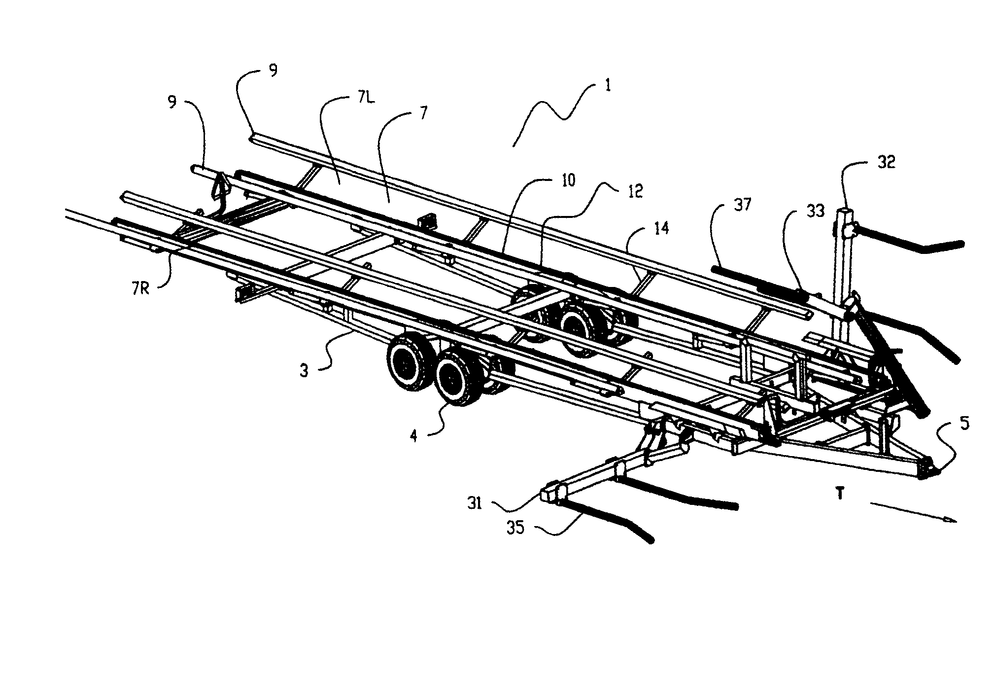
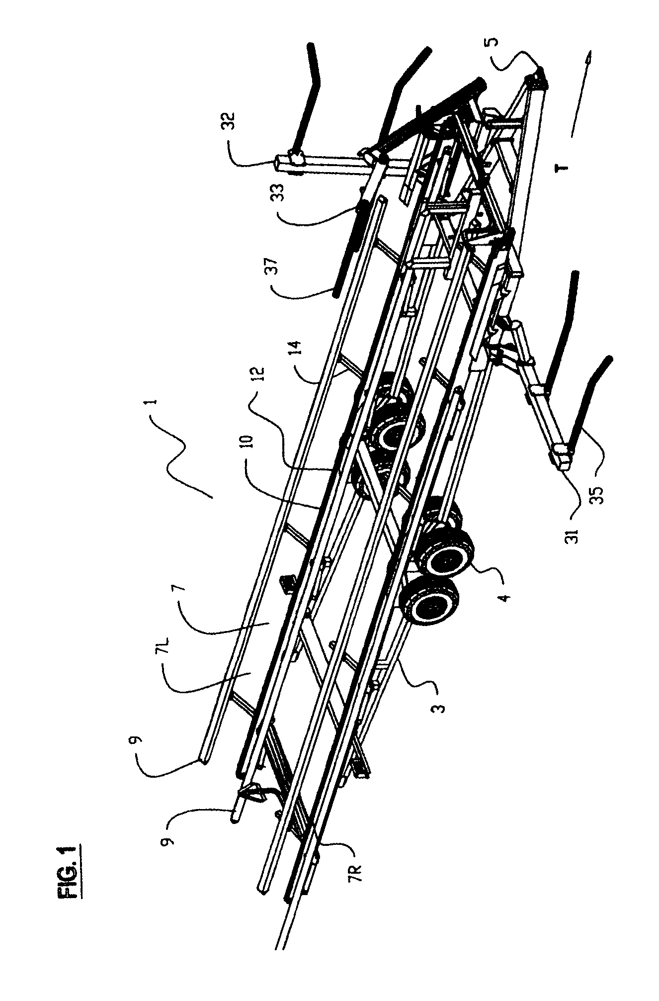
[0028]FIGS. 1, 4, 5, and 6 illustrate a trailer 1 for transporting cylindrical bales. The trailer 1 comprises a frame 3, and a hitch 5 attached to a front end of the frame 3 and adapted for attachment to a towing vehicle for movement in an operating travel direction T on the wheels 4 supporting the frame 3. Right and left conveyors 7R, 7L are oriented longitudinally along respective first and second sides of the frame 3 such that a cylindrical bale can rest on each conveyor 7. Bales are oriented on the conveyors 7 such that a longitudinal axis of the cylindrical bales is substantially aligned with the operating travel direction T, as seen in the front view of FIG. 4.

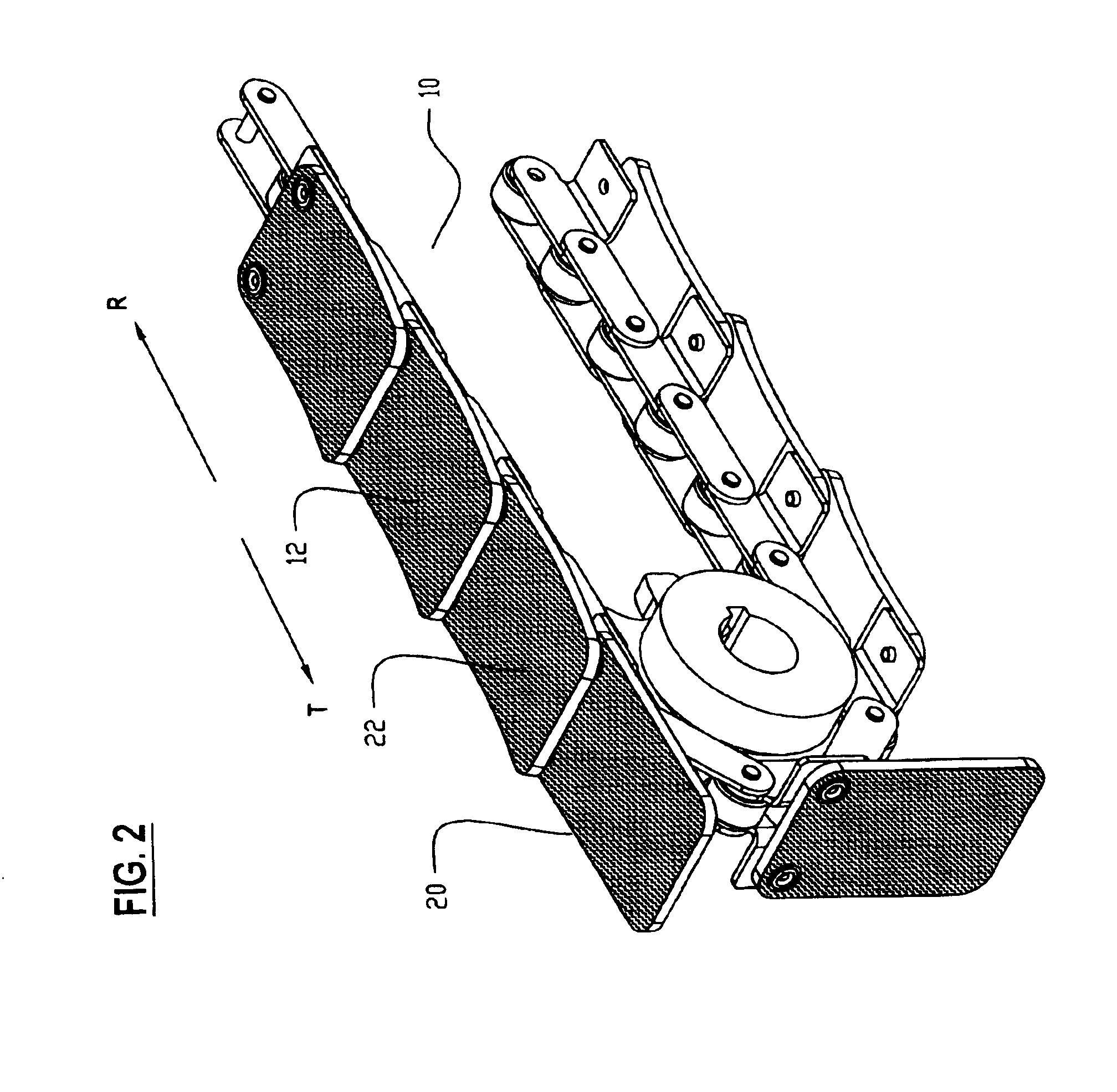
[0029]The conveyors 7 comprise a pair of substantially parallel conveyor rails 9 attached to the frame 3 and substantially aligned with the operating travel direction T and a conveyor chain 10 oriented parallel to the rails 9 and located between and below the rails 9 such that a bale can rest on a top load engaging face ...


PUM


Abstract

A trailer for transporting cylindrical bales comprises a pair of rails and a conveyor chain located between and below the rails such that a bale is maintained in position on the conveyor chain by the rails. The load engaging face of the conveyor chain comprises a plurality of resilient pads having a roughened surface to increase friction between the pads and the bale without protruding into the bale. The load engaging face can slide with respect to the bale. First and second loading arms are operative to raise first and second bales onto corresponding conveyors. A third loading arm raises the first bale from the first conveyor to allow the first loading arm to raise a third bale from the ground and position it on the first conveyor, and then lowers the first bale to rest on the second and third bales.

Description

[0001]This is a Continuation-in-Part of Application Ser. No. 10 / 180,722, filed Jun. 26, 2002 and Ser. No. 09 / 927,443 filed Aug. 13, 2001, now abandoned.[0002]This invention is in the field of towed vehicles for loading, transporting, and unloading large cylindrical bales, and conveyors therefore.BACKGROUND[0003]Various designs of transport vehicles for large cylindrical bales, commonly known as “round bales”, have been provided previously. In one arrangement, as disclosed in U.S. Pat. No. 3,942,666 to Pfremmer, a trailer carries two parallel rows of round bales. The bales are engaged by a lifting apparatus at a front end of a trailer and flipped rearwards onto the trailer. The bales land on a single longitudinal conveyor chain and are maintained in a position substantially centered on the conveyor chain by a confining wall on each side. The conveyor chain has lugs extending upward from the chain that extend into the bale and grab the bale to move it rearward with the conveyor chain ...

Claims


Application Information

Patent Timeline
Patent Type & Authority Patents(United States)
IPC IPC(8): A01D90/00A01D90/08
CPCA01D90/083
Inventor DELAURIER, RONALD T.
Owner BOURGAULT INDS
Why Eureka
Try Eureka