Orthodontic appliance

a technology for orthodontic appliances and convertible caps, applied in the field of orthodontic appliances, can solve the problems of corrosion around soldered parts, the peel strength of convertible caps is too hard to be controlled, and the effect of reducing the peeling load of convertible caps is almost constant, so as to achieve the effect of more controllable peeling load and less corrosion of convertible caps

Inactive Publication Date: 2005-05-03
TOMY CHOFU TOKIOTOKYO JP
View PDF7 Cites 7 Cited by
  • Summary
  • Abstract
  • Description
  • Claims
  • Application Information

AI Technical Summary

Benefits of technology

[0020]The present invention has been made in view of the above mentioned problems. Accordingly, it is an object of the present invention to provide an orthodontic appliance maintaining constant the peeling load of the convertible cap, irrespective of adhering conditions of the silver soldering material, enabling to easily peel the convertible cap from the archwire slot when needed, not weakening the peel strength of the convertible cap owing to conditions even in the mouth, and having no possibility of the convertible cap carelessly peeling off from the archwire slot.
[0033]In this case, if Au is contained, strength of the silver soldering material goes up, if Sn and Zn are contained, the soldering temperature of the silver soldering material may be lowered, and if Li is contained, wettability of the silver soldering material is made better.
[0034]In the thus composed orthodontic appliance, since the silver soldering material contains Ag 90% or more, the molten silver soldering material exhibits the good fluidity for soldering.
[0037]Accordingly, in the orthodontic appliance of the present invention, it is possible to reduce corrosion and elution of Cu from the soldered surface, and the Cu content eluting in the soldered interface between the main body of stainless steel and the convertible cap, and maintain a desired peel strength for a longer period than that of the related art.
[0039]In the present invention, as set forth in a third aspect thereof, since the silver soldering material contains no Cu, there are neither corrosion and elution of Cu from the soldered surface, nor elution of Cu content in the soldered interface between the main body of stainless steel and the convertible cap. Therefore, it is possible to maintain the peel strength for the longer period.
[0043]In the thus composed orthodontic appliance, in addition to the bonding strength of the silver soldering material and a particular shearing strength, the peel strength of the convertible cap can be more controlled by plastic deformation of the dovetail groove-like stepwise portions. Further, by being fitted in the dovetail groove, the peeling load of the convertible cap can be made almost constant, irrespective of the solder adhering conditions.

Problems solved by technology

Further, there is a case the soldering is too hard to peel off the convertible cap even with an exclusively used tool (not shown).
Since the deformation is dispersed per each of products or lots, it is extremely difficult to control the peel strength of the convertible cap effecting to the main body 72.
In addition, mainly owing to a galvanic phenomenon by different kinds of metals under conditions in the mouth, a problem has been present in corrosion occurring around soldered parts of the silver soldering material (BAg-8 or BAg-18) of the convertible cap 75.
Therefore, the soldered strength goes down as time-passing of a teeth curing period, and when a doctor exchanges the archwire, a problem occurs that the convertible cap 75 is carelessly peeled from the archwire slot 74.

Method used


Image

  • Orthodontic appliance
  • Orthodontic appliance
  • Orthodontic appliance

Examples


first embodiment

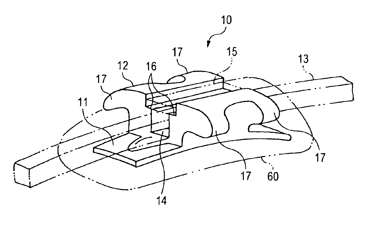
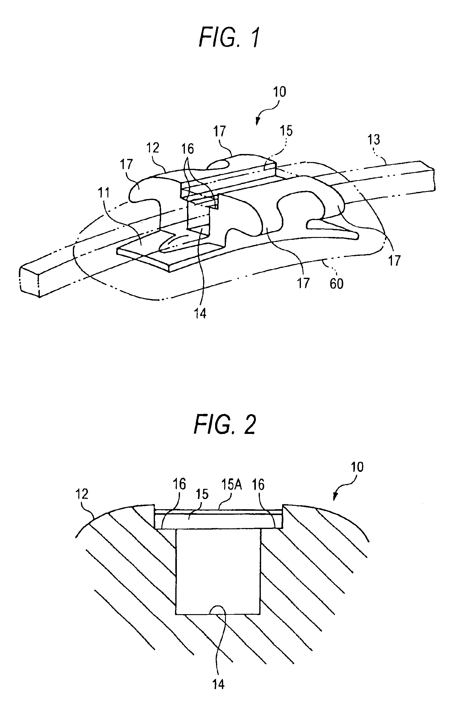
[0056]As shown in FIG. 1, the orthodontic appliance 10 of the first embodiment according to the present invention comprises a base 11, a main body 12, tie wings 17, an archwire slot 14, a convertible cap 15 and stepwise portions 16, 16. The base 11 is directly attached to tooth surfaces 60 or indirectly attached thereto by welding it to a correcting band. The main body 12 is equipped on the upper surface of the base 11. The tie wings 17 expand from the main body 12 toward a gingival side and an occlusion side. The archwire slot 14 is shaped in groove along mesiodistal direction in the main body 12, and enables to support an archwire 13 therein. The convertible cap 15 closes the archwire slot 14 along a length direction. The stepwise portions 16, 16 are provided at a pair of ends in the opening in cross section of the archwire slot 14 for receiving ends of the convertible cap 15.

[0057]The orthodontic appliance 10 is used to other than, for example, the first molars and the second mol...

second embodiment

[0090]FIGS. 5 and 6 show an orthodontic appliance 50 according to the present invention.

[0091]The orthodontic appliance 50 of the second embodiment has stepwise portions 56, 56 formed substantially in dovetail groove in cross section. A convertible cap 55 is almost trapezoidal in cross section of, e.g., the austenite stainless steel.

[0092]The convertible cap is inserted into the stepwise portions 56, 56 from the mesial side and soldered.

[0093]In the second embodiment, an angle 0 of inclination of the stepwise portions 56, 56 is around 10 to 15 degree with respect to a vertical line.

[0094]Similarly to the above mentioned first embodiment, the convertible cap 55 silver-plated 8 μm on one side is inserted into the stepwise portions 56, 56 from the mesiodistal direction, and soldered under the same conditions to the first embodiment.

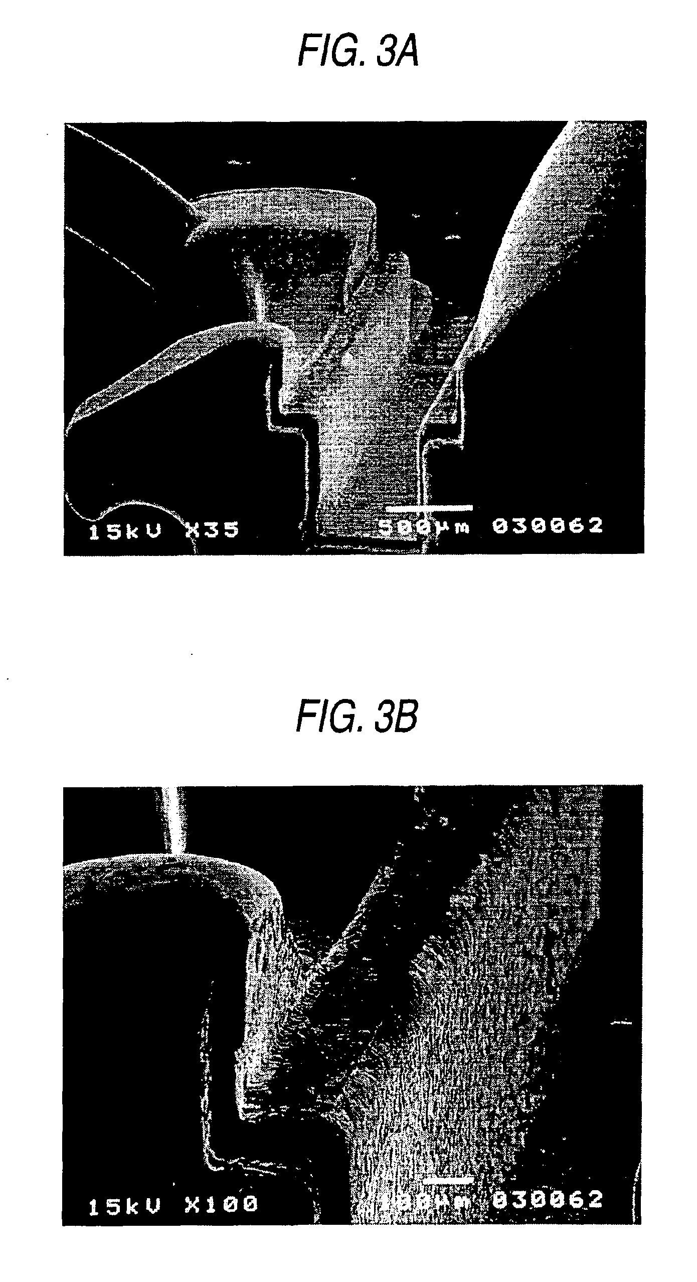
[0095]If the soldered convertible cap 55 is peeled from the mesial side by use of the exclusive tool, the end parts of the convertible cap 55 and the incli...

third embodiment

[0097]FIG. 7 shows an orthodontic appliance 80 according to the present invention.

[0098]The orthodontic appliance 80 of the third embodiment comprises a base 81, a main body 82, tie wings 87, a hook 88, a tube 89, an archwire slot 84, a convertible cap 85 and stepwise portions 86, 86. The main body 82 is equipped on the upper surface of the base 81. The tie wings 87 expand from the main body 82 toward a gingival side. The hook 88 is connected to the tie wings 87. The tube 89 is installed in opposition to the tie wings 87 and inserted with a face bow and an end of a lip bumper. The archwire slot 84 is shaped in groove along the mesiodistal direction in the main body 82, and enables to support an archwire therein. The convertible cap 85 closes the archwire slot 84 along the length direction. The stepwise portions 86, 86 are provided at an opening in cross section of the archwire slot 84.

[0099]The orthodontic appliance 80 is called as a convertible double tube to be used to the first m...


PUM


Abstract

An orthodontic appliance comprises a base, a main body equipped on one side of the base, an archwire slot furnished to the main body, a convertible cap closing the archwire slot along the length direction, and stepwise portions provided at ends of the archwire slot for receiving ends of the convertible cap. The convertible cap is fixedly soldered with a silver soldering material containing Ag 90% or more.

Description

BACKGROUND OF THE INVENTION[0001]1. Field of the Invention[0002]The present invention relates to an orthodontic appliance to be used in a mouth.[0003]2. Description of the Related Art[0004]The orthodontic appliance is attached to tooth surfaces for orthodontic treatment, and serve to transmit restoring force of an archwire to a root of the teeth.[0005]An orthodontic appliance 70 as shown in FIG. 10 comprises a base 71, a main body 72, an archwire slot 74, and a convertible cap 75. The base 71 is firmly attachable directly or indirectly to teeth. The main body 72 is equipped on one side of the base 71. The archwire slot 74 is shaped in groove along mesiodistal direction in the main body 72, and enables to support an archwire (not shown) therein. The convertible cap 75 closes the archwire slot 74 along the length direction.[0006]In related art, a pair of ends opening in cross section of the archwire slot 74 are provided with stepwise portions 76, 76 for receiving end parts of the conv...

Claims


Application Information

Patent Timeline
Patent Type & Authority Patents(United States)
IPC IPC(8): A61C7/28A61C7/00B23K35/30A61C7/14
CPCB23K35/3006A61C7/282A61C7/28
Inventor KAWAGUCHI, KOZONAGASE, KENJISHIGA, KIYOSHIORIKASA, MASAAKI
Owner TOMY CHOFU TOKIOTOKYO JP
Why Eureka
Try Eureka