Laparoscopic specimen extraction port

a specimen extraction port and laparoscopic technology, applied in the field of laparoscopic specimen extraction ports, can solve the problems of difficult for surgeons to extract specimens b, varied deleterious effects, and impaired specimen visualization, so as to reduce surgery time and post-operative recovery time

Inactive Publication Date: 2005-05-03
SHIMM PETER
View PDF22 Cites 151 Cited by
  • Summary
  • Abstract
  • Description
  • Claims
  • Application Information

AI Technical Summary

Benefits of technology

[0011]One aspect of the present invention, therefore, provides an improved laparoscopic trocar / port that reduces surgery time and post-operative recovery time.
[0012]An additional aspect of the present invention provides a laparoscopic trocar / port that substantially prevents a specimen from bunching in an endo-bag during extraction of the specimen from a patient.
[0013]A further aspect of the present invention provides a laparoscopic trocar / port that reduces the risk of rupturing the specimen or endo-bag during extraction of the specimen from a patient.
[0014]A further aspect of the present invention provides a laparoscopic trocar / port that reduces the risk of spreading infectious, bilious, and / or cancerous material into the patient's abdominal cavity and / or incision.

Problems solved by technology

This unfortunately often causes loss of pneumoperitoneum, leading to impaired visualization of the specimen 50 extraction process.
Unfortunately, as illustrated in FIG. 14, it is frequently difficult for the surgeon to extract the specimen 50 and endo-bag 60 through the relatively small incision 10.
Such bunching results in a variety of deleterious effects.
Expanding the incision 10 deleteriously increases postoperative pain, increases surgical blood loss, increases the risk of future dehiscence (opening) of the incision and / or herniation of the abdominal contents through the expanded incision 10, and reduces or eliminates the advantages of laparoscopic surgery.
Furthermore, the complications that often accompany the specimen 50 extraction procedure add significant operating room and anesthetic time to the surgery, which greatly increases the cost of the procedure to the hospital and the patient.

Method used


Image

  • Laparoscopic specimen extraction port
  • Laparoscopic specimen extraction port
  • Laparoscopic specimen extraction port

Examples


Embodiment Construction

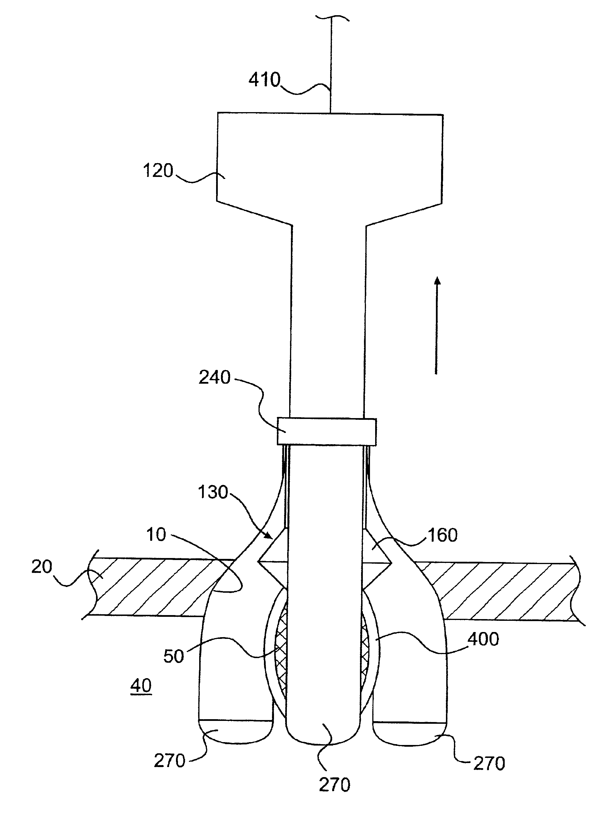
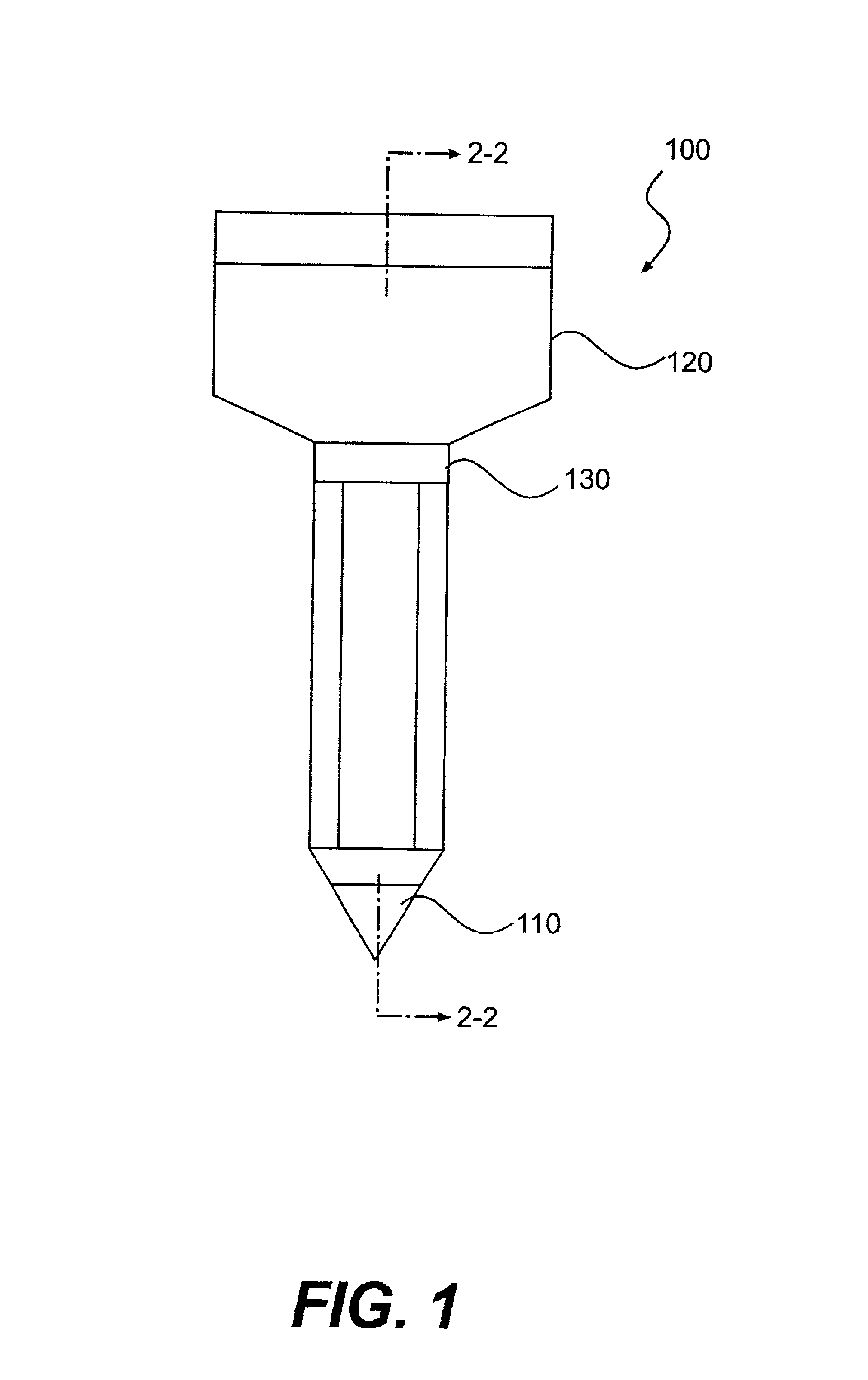
[0028]FIG. 1 is a side view of an LSEP 100 according to the present invention. The LSEP 100 includes a pointed trocar 110, a port 120, and a sheath 130. The LSEP 100 has expanded and contracted positions.

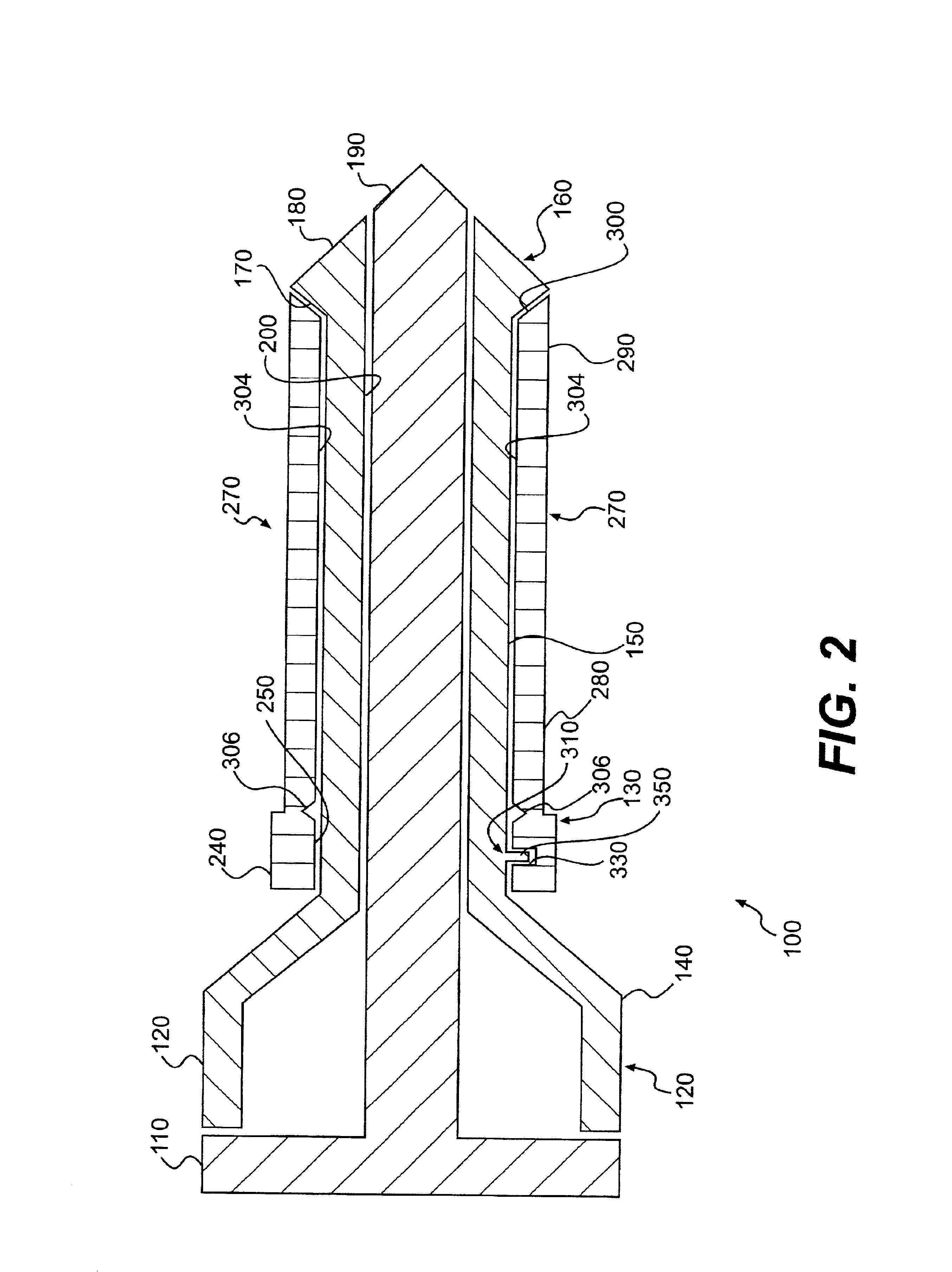
[0029]As illustrated in FIGS. 2 and 3, the port 120 is elongated and hollow. A rearward (or proximal) portion 140 of the port 120 is generally funnel-shaped and tapers radially-inwardly toward an intermediate portion 150. A flapper valve (not shown) like the conventional flapper valve 45 illustrated in FIGS. 15 and 16 is preferably disposed in the rearward portion 140 to preserve pneumoperitoneum during surgery when surgical instruments are not inserted through the port 120. The intermediate portion 150 is longitudinally elongated and preferably has a constant cross-section over its longitudinal length. As would be appreciated by one of ordinary skill in the art, however, the intermediate portion 150 need not have a constant cross-section over its longitudinal length. To the contrar...


PUM


Abstract

A laparoscopic surgical extraction port (LSEP) includes a port having a radially-enlarged distal end. A sheath having a plurality of circumferentially-spaced prongs is slidingly mounted onto the port. With the prongs contracted radially-inwardly and the LSEP in its contracted position, a surgeon inserts the LSEP into a patient's abdominal cavity through an incision. The surgeon then expands the LSEP by pulling the port rearwardly such that the radially-enlarged distal end expands the prongs radially-outwardly. The surgeon then positions a specimen and endo-bag in the funnel formed by the expanded prongs. The specimen, endo-bag, and prongs are thereafter simultaneously extracted through the incision. A radially-inward force that is applied to the prongs by the incision substantially prevents the specimen from bunching or rupturing during the extraction process.

Description

BACKGROUND OF THE INVENTION[0001]1. Field of the Invention[0002]The present invention relates generally to laparoscopic trocars / ports, and more specifically to laparoscopic specimen extraction ports (LSEPs) that prevent the extracted specimen from bunching up in an endoscopic specimen retrieval bag prior to removal through the abdominal wall, for example.[0003]2. Description of Related Art[0004]As illustrated in FIG. 11, during a typical abdominal laparoscopic surgery, a surgeon makes four or so small (typically about 2 cm) incisions 10 in the abdominal wall 20 of the patient. The surgeon positions a trocar 22 (shown in FIGS. 15 and 16) into an axial hole 26 in a laparoscopic port 30 to facilitate insertion of the port 30 into the incision 10. After inserting the trocar 22 and port 30 through the incision 10, the surgeon removes the trocar 22 to allow insertion of surgical instruments (e.g., grasping instrument 80) into the abdominal cavity 40 through the axial hole 26 in the port 3...

Claims


Application Information

Patent Timeline
Patent Type & Authority Patents(United States)
IPC IPC(8): A61B17/34A61B19/00A61B17/00
CPCA61B17/3439A61B2017/347A61B2017/00004A61B19/38A61B90/40
Inventor SHIMM, PETER
Owner SHIMM PETER
Why Eureka
Try Eureka