Cyclic membrane separation process
a cyclic membrane and membrane technology, applied in the field of cyclic membrane separation, can solve the problems of air leakage contributing to the pressure increase in the tank, and the pressure cannot be maintained
Inactive Publication Date: 2005-05-03
CMS TECH HLDG
View PDF34 Cites 13 Cited by
- Summary
- Abstract
- Description
- Claims
- Application Information
AI Technical Summary
Benefits of technology
[0026]The novel process and system are effective to reduce the cumulative amount per cycle of less preferentially permeable gas components in the permeate gas mixture below that which is produced when no air is charged into the membrane module or when vacuum is not drawn in the membrane module, as the case may be.
Problems solved by technology
Few controls were aimed at curbing fugitive emissions such as emissions of VOC incidental to dispensing fuel from bulk storage tanks and to storing the fuel in the tanks.
The returning gas mixture from dispensing operations, as well as other factors, caused pressure to build up in the ullage over time.
In addition to the gas buildup mentioned earlier, air in-leakage contributes to pressure increase in the tank.
Negative pressure thus can only be maintained if gas is exhausted to the environment from time to time.
However, it is necessary to strip all or a portion of the VOC from the exhausted gas.
Otherwise, the VOC in the discharged gas defeats the purpose of the pollution control system.
Although the separation membrane selectively permeates oxygen and nitrogen, it does not absolutely reject VOC compounds.
As a result, the time-averaged quantity of VOC compounds discharged to the air is still unacceptably high.
Method used
View moreImage
Smart ImageViewing Examples

Examples
examples
[0072]This invention is now illustrated by examples of certain representative embodiments thereof, wherein all parts, proportions and percentages are by volume unless otherwise indicated. All units of weight and measure not originally obtained in SI units have been converted to SI units.
Login to view more PUM
 Abstract
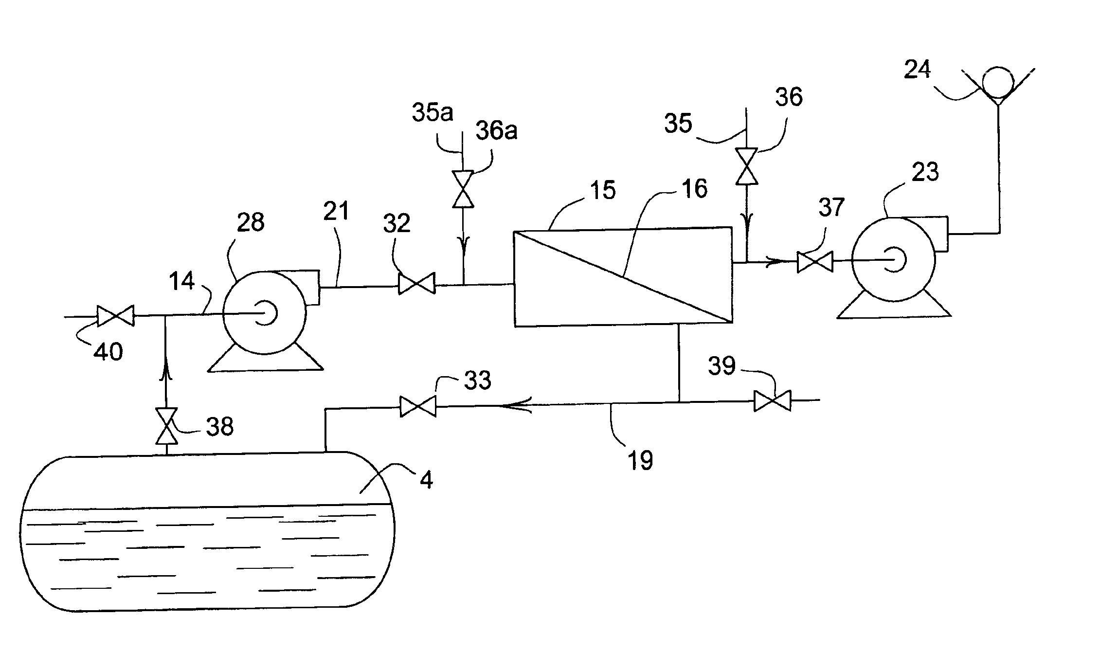
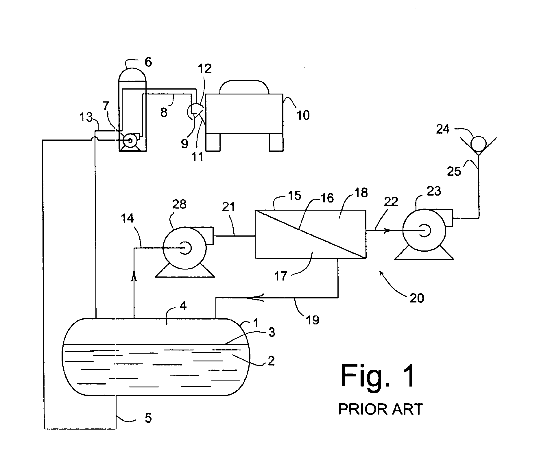
A cyclic process for controlling environmental emissions of volatile organic compounds (VOC) from vapor recovery in storage and dispensing operations of liquids maintains a vacuum in the storage tank ullage. In the first part of a two-part cyclic process ullage vapor is discharged through a vapor recovery system in which VOC are stripped from vented gas with a selectively gas permeable membrane. In the second part, the membrane is inoperative while gas pressure rises in the ullage. In one aspect of this invention, a vacuum is drawn in the membrane separation unit thus reducing overall VOC emissions.
Description
[0001]This application claims benefit of priority of U.S. provisional application Ser. No. 60 / 442,291 filed Jan. 24, 2003.[0002]Support was provided under Department of Energy award DE-FG02-00ER82976. The U.S. government has rights in this patent application.FIELD OF THE INVENTION[0003]This invention relates to a cyclic process using a selectively gas permeable membrane to separate a component from a gas mixture. More specifically, it relates to a membrane separation process useful for recovery of volatile organic compounds emitted from storage tanks utilizing a membrane comprising a selectively gas permeable membrane polymer. The process includes repetitively cycling between flow and non-flow of gas through the membrane.BACKGROUND OF THE INVENTION[0004]Liquid volatile organic compounds (“VOC”) are stored and dispensed from tanks. A very common example is in the field of distribution of combustion engine fuel such as gasoline for fueling automobile and aircraft engines. The storage ...
Claims
Login to view more Application Information
Patent Timeline
 Patent Type & Authority Patents(United States)
IPC IPC(8): B01D53/22
CPCB01D53/22B01D2257/708Y02A50/20
Inventor NEMSER, STUART M.
Owner CMS TECH HLDG
- R&D Engineer
- R&D Manager
- IP Professional
Why Eureka
- Industry Leading Data Capabilities
- Powerful AI technology
- Patent DNA Extraction
Try Eureka
Browse by: Latest US Patents, China's latest patents, Technical Efficacy Thesaurus, Application Domain, Technology Topic.
© 2024 PatSnap. All rights reserved.Legal|Privacy policy|Modern Slavery Act Transparency Statement|Sitemap