Holonomic platform for a robot

a technology of holonomy and robot, which is applied in the direction of programme control, distance measurement, instruments, etc., can solve the problems of affecting the drive ball and supporting bearing, and the movement of the robot may develop a wobbl

Inactive Publication Date: 2005-05-03
JONATA SUB TWO INC +1
View PDF38 Cites 211 Cited by
  • Summary
  • Abstract
  • Description
  • Claims
  • Application Information

AI Technical Summary

Problems solved by technology

Unfortunately, the brackets prevent continuous contact between a single roller and the underlying surface of the robot.
If the relative phase of the rollers changes, the movement of the robot may develop a wobble.
Additionally, the out of phase rotation of the transmission rollers may create undesirable impact forces and resultant stresses on the drive ball and supporting bearings.

Method used


Image

  • Holonomic platform for a robot
  • Holonomic platform for a robot
  • Holonomic platform for a robot

Examples


Embodiment Construction

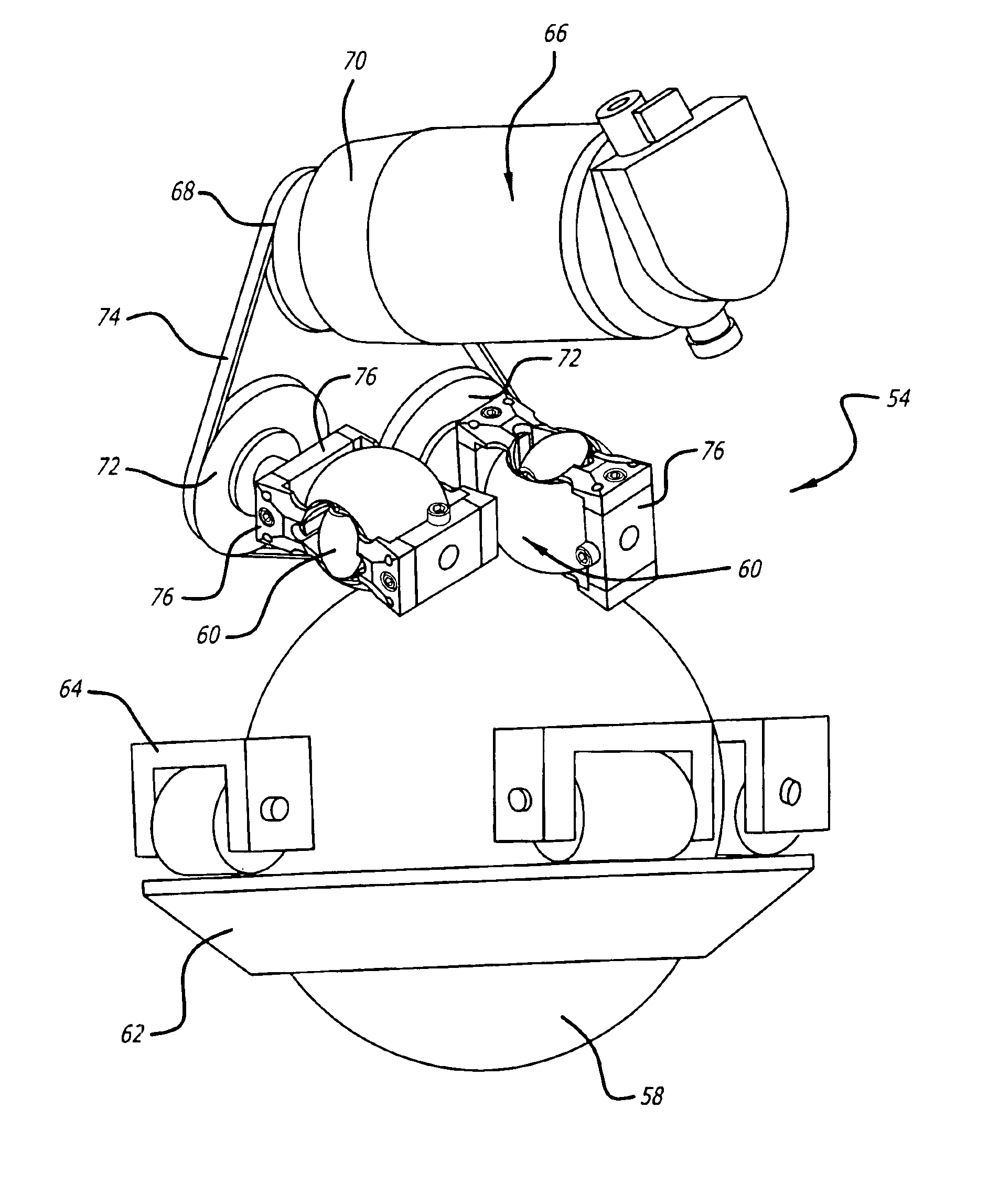
[0019]Disclosed is a robot that includes a plurality of roller assemblies. Each roller assembly may include a transmission roller that is spun by a drive mechanism to rotate a drive ball. Rotation of the drive ball propels the robot across a surface. The transmission roller is in continuous contact with the drive ball. Continuous contact between the roller and ball eliminates roller induced wobble in the robot movement, reduces impact forces and resultant stress within the roller assembly and allows for the use of a drive ball that is more compliant than balls in the prior art.

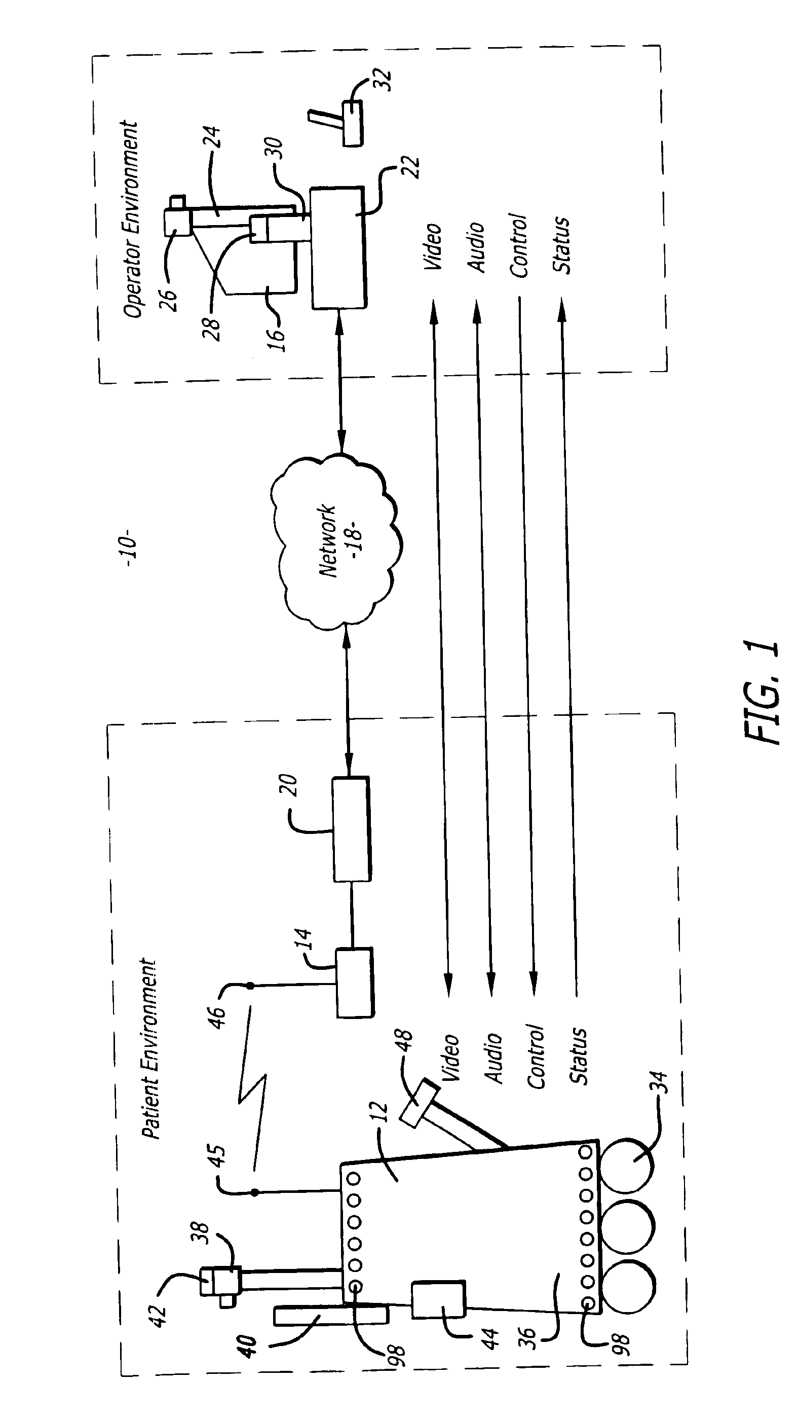
[0020]Referring to the drawings more particularly by reference numbers, FIG. 1 shows a robotic system 10. The robotic system 10 includes a robot 12, a base station 14 and a remote control station 16. The remote control station 16 may be coupled to the base station 14 through a network 18. By way of example, the network 18 may be either a packet switched network such as the Internet, or a circuit switched netwo...


PUM


Abstract

A robot that includes a plurality of roller assemblies. Each roller assembly may include a transmission roller that is spun by a drive mechanism to rotate a drive ball. Rotation of the drive ball propels the robot across a surface. The transmission roller is in continuous contact with the drive ball. Continuous contact between the roller and ball eliminates roller induced wobble in the robot movement, reduces impact forces and resultant stress within the roller assembly and allows for the use of a drive ball that is more complaint than balls in the prior art.

Description

BACKGROUND OF THE INVENTION[0001]1. Field of the Invention[0002]The subject matter disclosed generally relates to a drive roller assembly for a mobile robot.[0003]2. Background Information[0004]There have been developed various mobile robots that have a variety of different drive mechanisms to power the robot across a surface. For example, U.S. Pat. No. 5,374,879 issued to Pin et al., discloses a holonomic platform that includes three separate drive roller assemblies. Each drive roller assembly includes a pair of rollers that are spun by a drive motor. The rollers periodically make contact with the ground to exert a frictional force that propels the robot across a surface.[0005]One or more of the three rollers assemblies is typically powered to drive the robot in a desired direction. The rollers of each roller assembly are coupled to the motor by a bracket. The bracket allows passive movement of the rollers that are not driven by a motor. Unfortunately, the brackets prevent continuo...

Claims


Application Information

Patent Timeline
Patent Type & Authority Patents(United States)
IPC IPC(8): B25J5/00B60B19/14B62D57/00
CPCB25J5/007B62D57/00B60B19/14
Inventor LABY, KEITH PHILLIP
Owner JONATA SUB TWO INC
Why Eureka
Try Eureka