High performance digital loop diagnostic technology

a diagnostic technology and high-performance technology, applied in the field of high-performance digital loop diagnostic technology, diagnosis and recovery, can solve the problems of data corruption, general limited capacity, data corruption,

Inactive Publication Date: 2005-05-03
VIXEL CORP
View PDF13 Cites 26 Cited by
  • Summary
  • Abstract
  • Description
  • Claims
  • Application Information

AI Technical Summary

Problems solved by technology

These capabilities have generally been limited to high level observation of the data traveling around the loop.
More specifically, these prior art diagnostic capabilities may indicate that certain packets of data are corrupted in addition to indicating the point of origination of the corrupted data.
Therefore, it is possible for the data to have been corrupted at any point along this path.
An unsuspecting system administrator who immediately assumes that S2 is responsible for the corrupted data can waste enormous effort in attempting to diagnose a problem which may occur anywhere along the loop between S2 and S1.
Thus, the use of an analyzer in such a scenario is disadvantageous.
Moreover, as another disadvantage, it is important to note that the use of the analyzer is intrusive.
This fact can cause severe complications in some cases.
Unfortunately, however, as soon as the original connections are restored, the masked problem will return.
As can be appreciated, this disadvantageous hit or miss technique is likely to be a long process.
Moreover, each time a connection is disturbed to insert the analyzer, the loop is taken out of service.
The process can also be expensive just due to replacement of any number of perfectly good, but suspect components.
Just through the use of an analyzer, it is very difficult to gain a complete “picture” of what is going on in the loop which may, in fact, represent the only way in which a particular problem may be understood.
Not only is the analyzer ineffective in many cases, it is also typically expensive.

Method used


Image

  • High performance digital loop diagnostic technology
  • High performance digital loop diagnostic technology
  • High performance digital loop diagnostic technology

Examples


Embodiment Construction

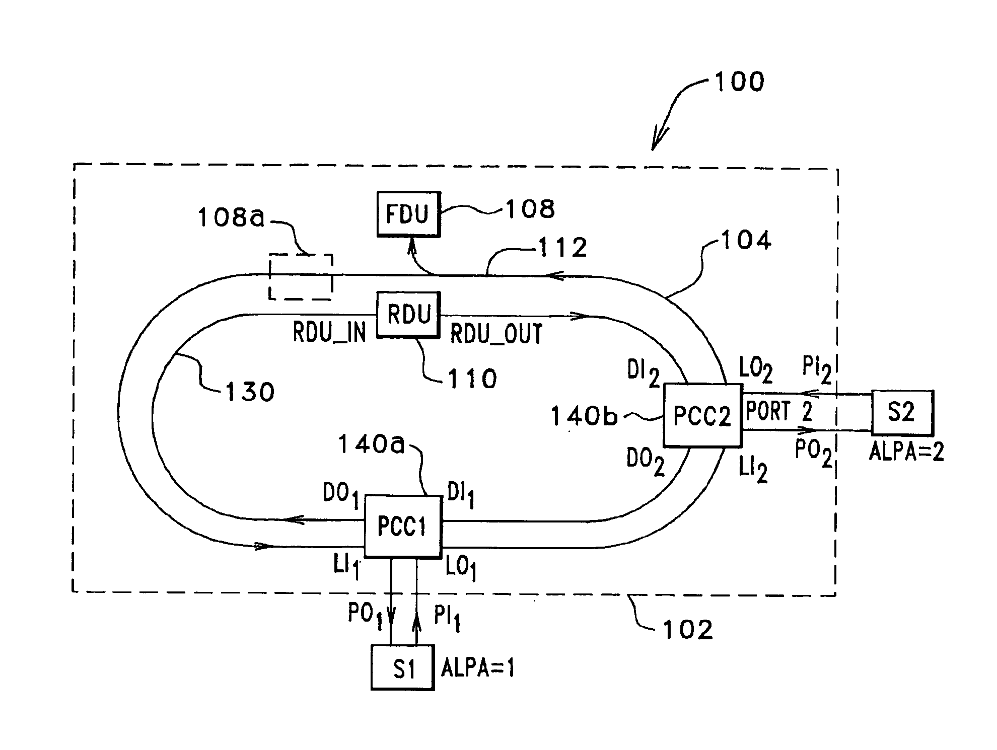
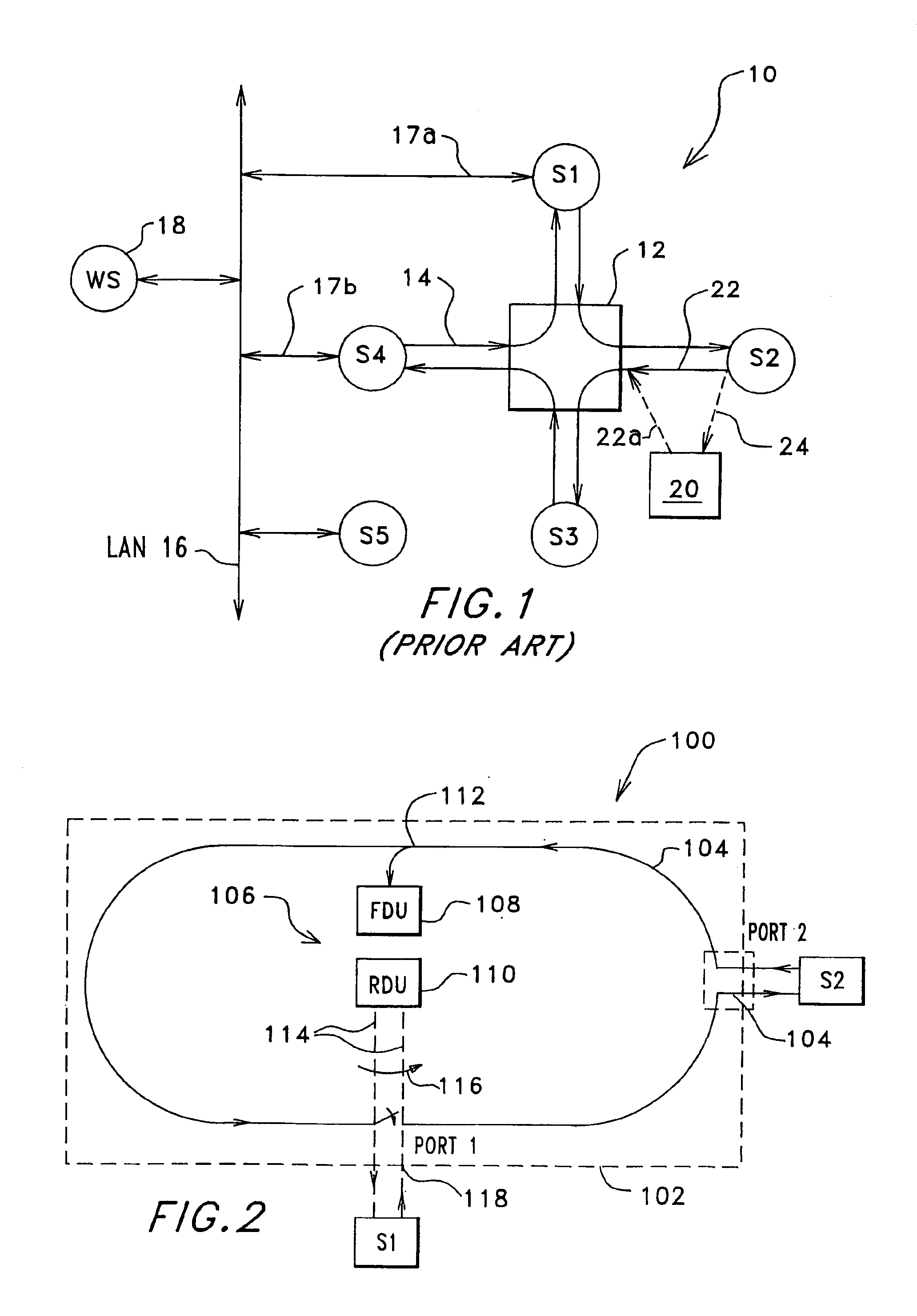
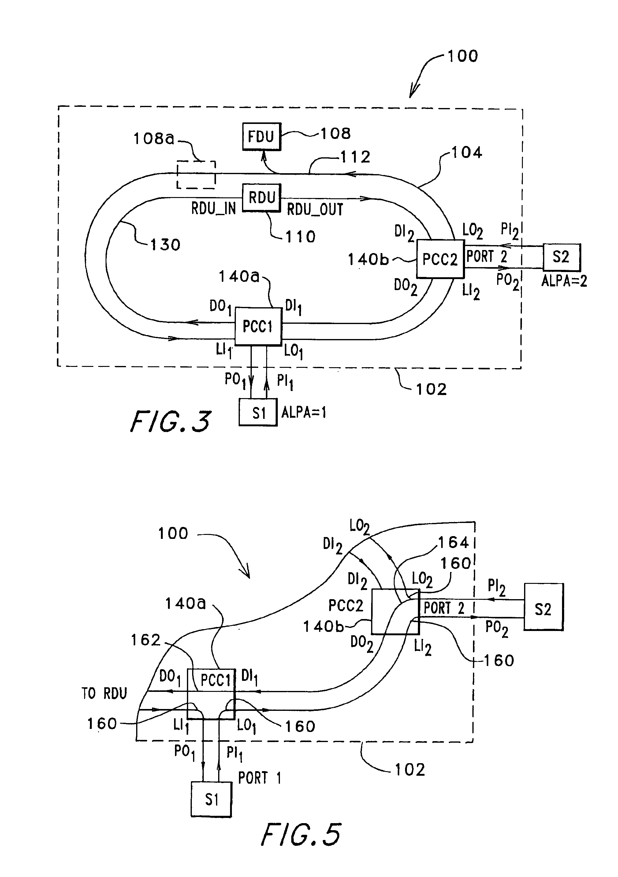
[0045]Attention is immediately directed to FIG. 2 which illustrates a digital system generally indicated by the reference numeral 100 including a hub 102 which is manufactured in accordance with the present invention. It is noted that like reference numbers are used throughout the various figures to refer to like components wherever possible. System 100 includes a main loop 104 which uses Fibre Channel protocol. However, it should be appreciated that loops which employ other protocols such as, for example, Token Ring and Fibre Distributed Data Interface (FDDI) may benefit from the teachings herein. Loop 104 interconnects stations S1 and S2 such that digital data in accordance with Fibre Channel protocol standards flows around the loop in the direction indicated by a number of arrowheads. Only two stations are illustrated as being interconnected by loop 104 for purposes of simplicity. Hubs, such as hub 102 are configured with ports by which stations such as S1 and S2 may be connected...


PUM


Abstract

Methods and associated hub arrangements are described for use in diagnosis and recovery in high performance digital loops such as, for example, those seen in Fiber Channel systems. In one system having a hub configured for interconnection of a plurality of stations as part of a digital system such that digital data flows between the stations based on operational status of the system, an arrangement forms part of the hub which arrangement is connectable at points within the hub and between at least two different pairs of the stations for, monitoring certain characteristics of the data in a way which provides for non-invasive identification of one or more conditions related to the operational status of the system.

Description

[0001]This application claims benefit to U.S. provisional 60 / 108,471 filed Nov. 14, 1998.BACKGROUND OF THE INVENTION[0002]The present invention relates generally to the field of digital loop technology utilizing a hub structure and, more particularly, to the field of diagnosis and recovery using a hub in high performance digital loops such as, for example, those hubs seen in Fibre Channel systems.[0003]The value of the digital loop in high performance systems such as Fibre Channel is without question. Moreover, the use of such a loop has proven to be enhanced through the use of a hub which serves as a central connection point for the loop. In such a configuration, the loop is said to be in the form of a “star”. Initial development of hubs saw what may be referred to as an unmanaged or “dumb” hub. As these terms indicate, such hubs served much in the manner of a patch panel, devoid of any monitoring capability as to the data passing through the hub.[0004]Still considering the hub tec...

Claims


Application Information

Patent Timeline
Patent Type & Authority Patents(United States)
IPC IPC(8): H04L12/26H04L12/42
CPCH04L12/42H04L43/10H04L43/0817
Inventor JOHNSON, BRUCE E.HAMMOND-DOEL, THOMAS J.JOLLAY, DONNA M.THOMPSON, MICHAEL I.
Owner VIXEL CORP
Why Eureka
Try Eureka