Rifle comprising a stock, a forearm and a barrel

a technology of forearm and barrel, which is applied in the direction of small arms, shoulder-fired small arms, weapons components, etc., to achieve the effect of less manufacturing cos

Inactive Publication Date: 2005-05-10
ORTH MANFRED +2
View PDF16 Cites 25 Cited by
  • Summary
  • Abstract
  • Description
  • Claims
  • Application Information

AI Technical Summary

Problems solved by technology

The disadvantage of this rifle is that after each assembly the barrel adopts another position relative to the stock so that the aiming situation is a different one after each assembly as a result thereof.
Accordingly, the barrel needs only be fastened to the stock through the forearm in the non-repeated condition i.e., during repetition because during repetition there is a risk that the chamber body or the cartridge inserted in the chamber pulls the barrel forward and out.

Method used


Image

  • Rifle comprising a stock, a forearm and a barrel
  • Rifle comprising a stock, a forearm and a barrel
  • Rifle comprising a stock, a forearm and a barrel

Examples


Embodiment Construction

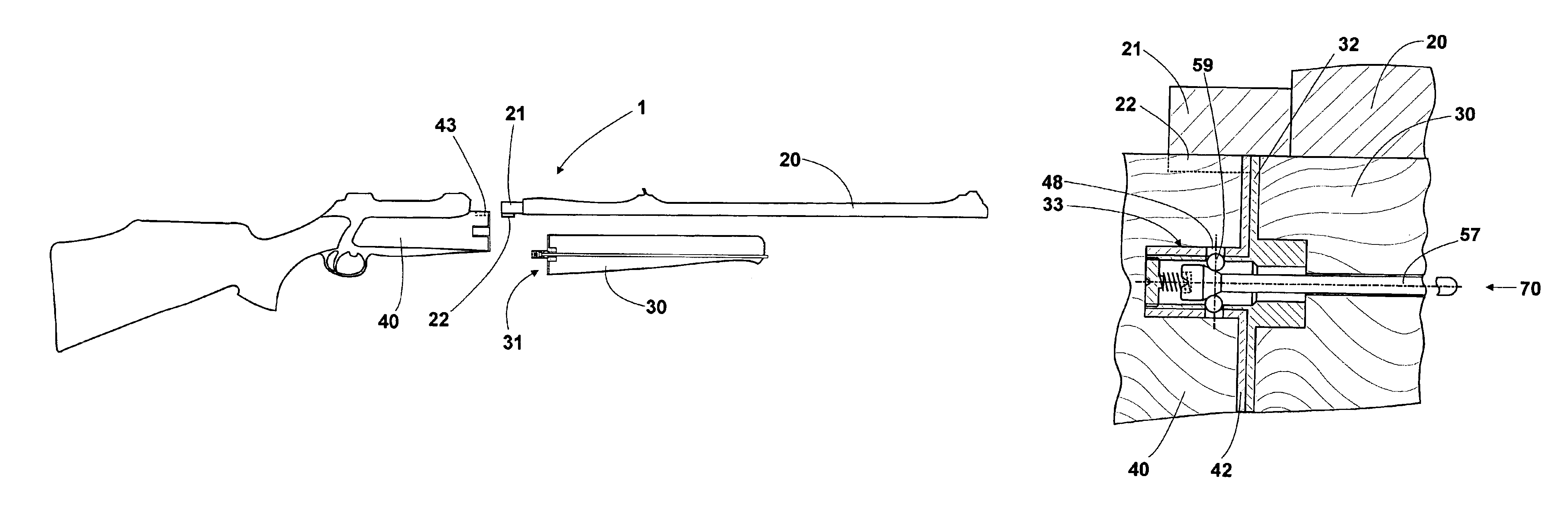
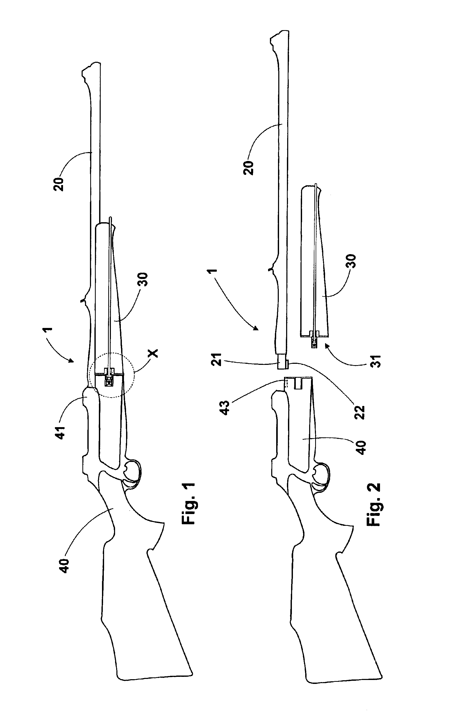
[0016]The rifle indicated generally at 1 shows the barrel 20, the forearm 30 and the stock 40. The stock 40 has the housing 41, the stock 40 being provided in the region of the housing 41 with a groove 43 oriented parallel to the longitudinal axis of the stock 40. The barrel 20 is provided with a sleeve 21 and with a nose 22 disposed beneath the sleeve for slidable reception into the groove 43. After the forearm 30 has been attached, the groove 43 is blocked by the front side 31 of the forearm 30 in such a manner that the nose 22 of the barrel cannot slip out of the groove 43.

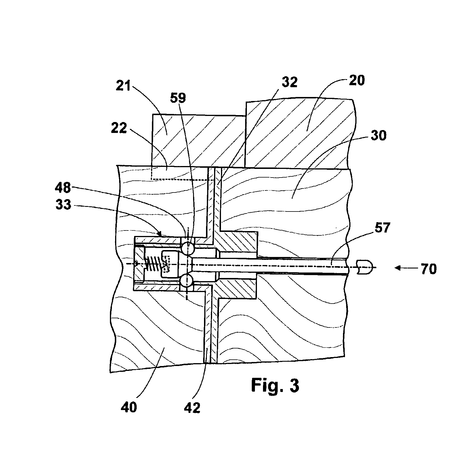
[0017]The FIGS. 3 and 4 more specifically show the locking of the forearm 30 to the stock 40. On its front side (arrow 31) the forearm 30 has a front plate 32. The front plate 32 comprises the sleeve-like projection 33 that receives the locking device 50. The stock 40 also has a front plate 42 which abuts on the front plate 32 of the forearm when the forearm and the stock are assembled. The front plate 42 of th...


PUM


Abstract

The subject matter of the invention is a rifle (1) comprising a stock (40), a forearm (30) and a barrel (20), the barrel (20) being releasably connectable to the stock (40) and said barrel (20) being fastenable to said stock (40) by bringing the forearm (30) into locking engagement with said stock (40) by means of a locking device (50), the locking device (50) being spring-loaded and the spring (60) being compressed by an actuation member (57) for the purpose of unlocking.

Description

FIELD OF THE INVENTION[0001]The present invention relates to a rifle comprising a stock, a forearm and a barrel, the barrel being releasably connectable to the stock and fastenable to said stock by bringing the forearm into locking engagement with said stock by means of a locking device.[0002]Experts use the term “takedown rifle” when speaking of a rifle the barrel of which is detachable from the stock. Such type rifles, the barrel of which may be separated from the stock, are particularly suited for use when a rifle must be transported or when the barrel is wished to be interchangeable.DESCRIPTION OF THE PRIOR ART[0003]In a prior art takedown rifle the barrel is clampingly received by the chamber of the stock. For this purpose the chamber has a lengthwise slotted sleeve-like projection which is provided with clamping screws in the region of the slot. Said clamping screws serve to vary the width of the slot so that the barrel may be clampably fastened in the slotted sleeve-like proj...

Claims


Application Information

Patent Timeline
Patent Type & Authority Patents(United States)
IPC IPC(8): F41A21/00F41A21/48F41C7/00F41C7/11F41A11/00
CPCF41C7/11F41A21/484F41A11/04
Inventor ORTH, MANFRED
Owner ORTH MANFRED
Why Eureka
Try Eureka