Electro-mechanical actuator

a technology of electromechanical actuators and actuators, applied in the direction of valve operating means/release devices, wing accessories, etc., can solve the problems of increasing electrical power requirements to achieve sufficient power output, affecting the overall system efficiency, and affecting the operation of the engine. size and power requirements,

Inactive Publication Date: 2005-05-10
STONERIDGE CONTROL DEVICES
View PDF50 Cites 43 Cited by
  • Summary
  • Abstract
  • Description
  • Claims
  • Application Information

AI Technical Summary

Problems solved by technology

The higher friction and lower efficiency worm drive results in lower overall system efficiency, and greater electrical power requirements to achieve sufficient power output.
Although this alleviates, in part, the design concerns, the problems associated with engine size and power requirements remain.
Utilizing a smaller motor, however, sacrifices motor power, speed and efficiency.
Not only are such failures common, they occur without any prior notice.

Method used


Image

  • Electro-mechanical actuator
  • Electro-mechanical actuator
  • Electro-mechanical actuator

Examples


Embodiment Construction

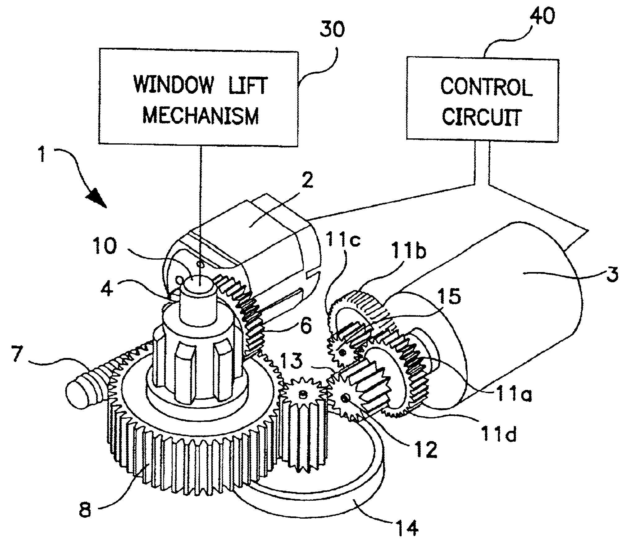
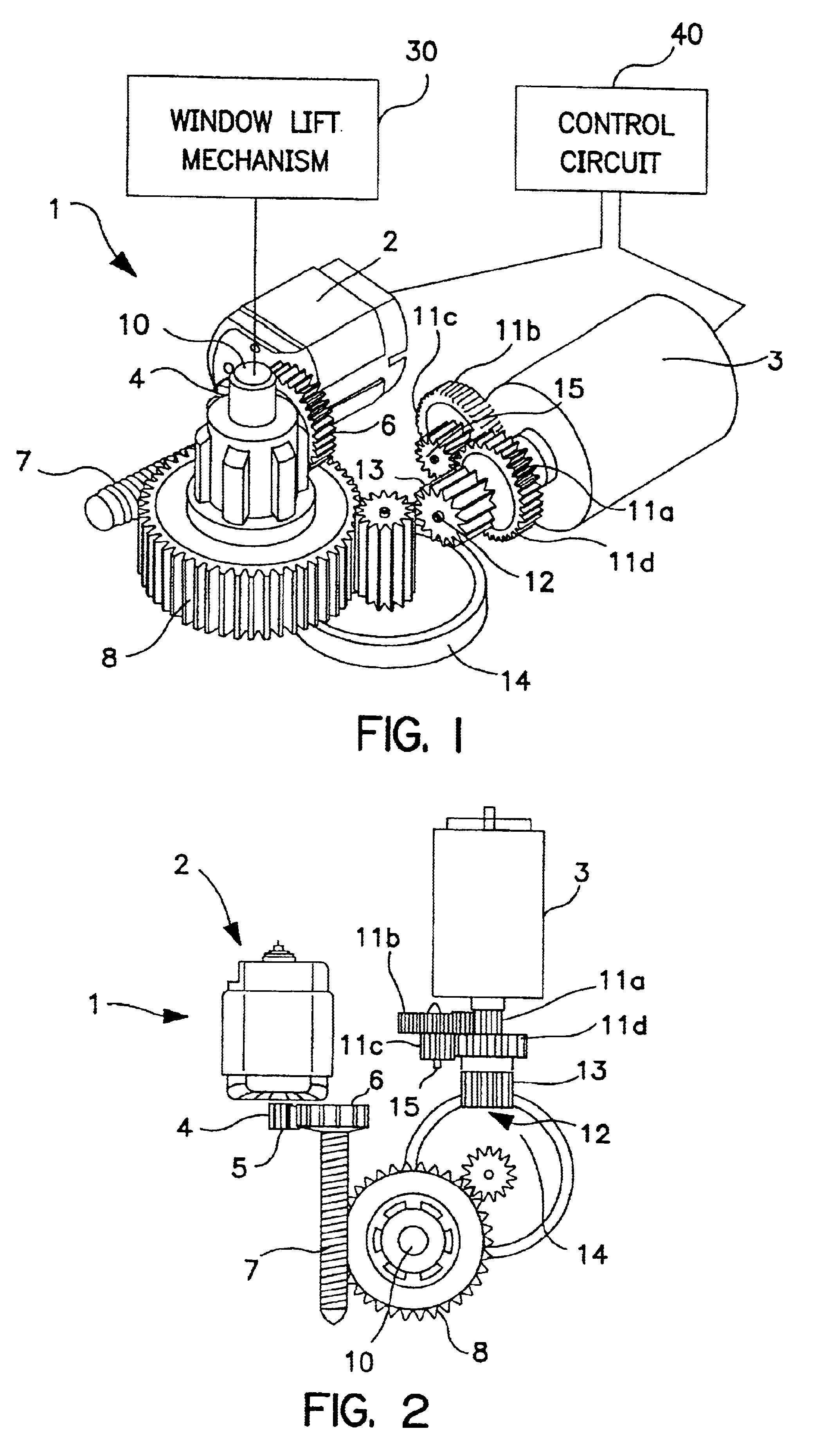
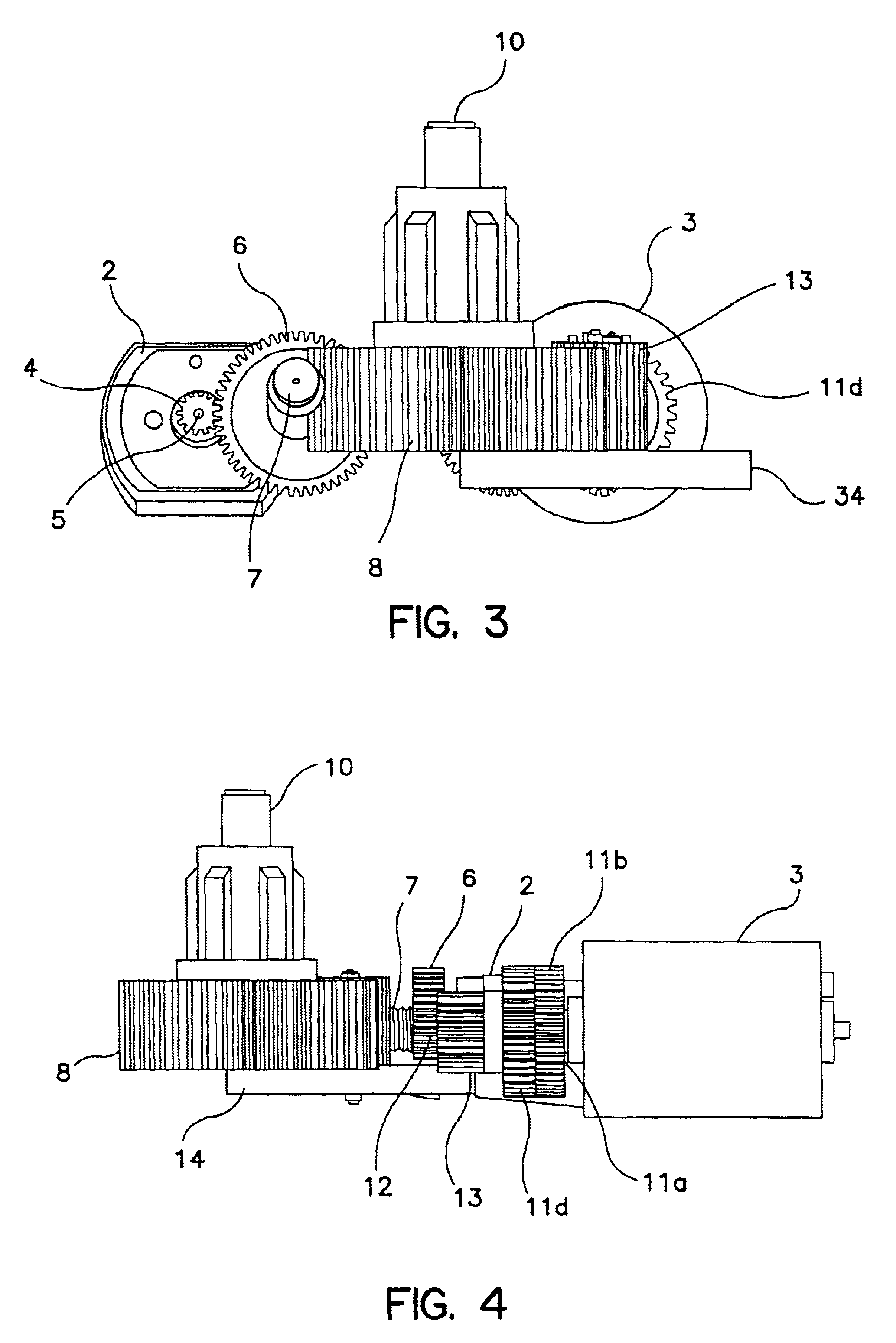
[0041]Referring to FIGS. 1 through 4, an exemplary actuator 1 consistent with the invention is illustrated. As shown, the actuator 1 includes two electric motors 2 and 3. A control circuit 40 controls energization of the motors. The control circuit may include, for example, a simple switch, or more complex arrangement providing pinch resistance, express open / close, etc.

[0042]Motor 2 has a first drive pinion 4 disposed about its output shaft 5 which engages worm wheel 6 attached to worm gear 7. The worm gear 7 engages spur gear 8 for driving an actuator output shaft 10. The output shaft is provided in driving relationship to a mechanism to be driven, e.g. a window lift mechanism 30. The window lift mechanism may include, for example, a conventional scissor lift, a cable and pulley mechanism, etc. The present invention is not, however, limited to window lift applications. In fact, an actuator consistent with the invention may be provided to drive a wide variety of mechanisms for achie...


PUM


Abstract

An electro-mechanical actuator including a plurality of motors for driving an output shaft. The actuator may be incorporated into a window lift mechanism, such as a mechanism including a dual rack and pinion assembly. According to another aspect of the invention there is provided a variety of anti-back-drive mechanisms, e.g. clutches. A clutch according to one embodiment includes locking pawls that resist back-drive. In another embodiment, locking cams rotate relative to a carrier to resist back-drive. An actuator consistent with the invention may incorporate an impact mechanism including a flexible carrier. The carrier flexes to prevent impact forces at an output gear train from coupling to an input gear train.

Description

CROSS-REFERENCE TO RELATED APPLICATIONS[0001]The present application claims the benefit of the filing dates of U.S. Provisional Application Nos. 60 / 176,847 and 60 / 178,593 filed Jan. 19, 2000 and Jan. 28, 2000, respectively, the teachings of which are incorporated herein by reference.FIELD OF THE INVENTION[0002]The present invention relates generally to an electro-mechanical actuator, and, in a particular embodiment, to an actuator for raising and lowering a window such as an automobile window.BACKGROUND OF THE INVENTION[0003]Electro-mechanical actuators are commonly used for a wide variety of applications. In an automotive setting, for example, actuators may be used for raising and lowering windows, for opening and closing sunroofs, controlling windshield wipers, etc. In a power window application, for example, an actuator may be located in each door assembly having an operable window, and usually includes an electric motor of some sort and a drive mechanism for raising and lowering...

Claims


Application Information

Patent Timeline
Patent Type & Authority Patents(United States)
IPC IPC(8): E05F15/16F16H37/06H02K7/116E05F11/38E05F11/42H02K7/10H02K16/00E05F11/40E05F11/50
CPCE05F15/697F16H37/065H02K7/1163H02K7/1166E05F11/405E05F11/505E05Y2201/72E05Y2900/55F16H2035/005H02K7/10H02K16/00E05Y2800/242Y10T74/19014Y10T74/18792Y10T74/18808Y10T74/19828Y10T477/23E05F11/423
Inventor SPAZIANI, PHILLIPMURRAY, JOHNLASKIN, IRVINGBISHAI, MACRAMBEISHLINE, ERICHOLLOWAY, JOHNFARMER, BILL
Owner STONERIDGE CONTROL DEVICES
Why Eureka
Try Eureka