Engine and personal watercraft equipped with engine

a technology of engine and watercraft, which is applied in the direction of machines/engines, steam power plants, auxiliary lubrication, etc., can solve the problems that the high-capacity scavenging pump for returning the oil of the cylinder head into the oil tank chamber becomes unnecessary, and achieves efficient arranging of the engine and efficient use of the dead space

Inactive Publication Date: 2005-05-10
KAWASAKI MOTORS LTD
View PDF15 Cites 25 Cited by
  • Summary
  • Abstract
  • Description
  • Claims
  • Application Information

AI Technical Summary

Benefits of technology

The objective of this invention is to create an engine that can be placed within a limited amount of space on a person's watercraft. This allows for efficient use of all available spaces when designing the engine. Additionally, it provides a more compact and streamlined appearance compared to traditional engines used on personal watercraft.

Problems solved by technology

The technical problem addressed in this patent relates to limited design flexibility due to the small size of the engine room in personal watercraft containing a dry-sump engine with a separate oil tank chamber. There is insufficient space available for arranging all required components, resulting in a complicated structure and requiring excessive space.

Method used


Image

  • Engine and personal watercraft equipped with engine
  • Engine and personal watercraft equipped with engine
  • Engine and personal watercraft equipped with engine

Examples


Embodiment Construction

[0054]Hereinafter, a preferred embodiment of the present invention will be described with reference to the accompanying drawings.

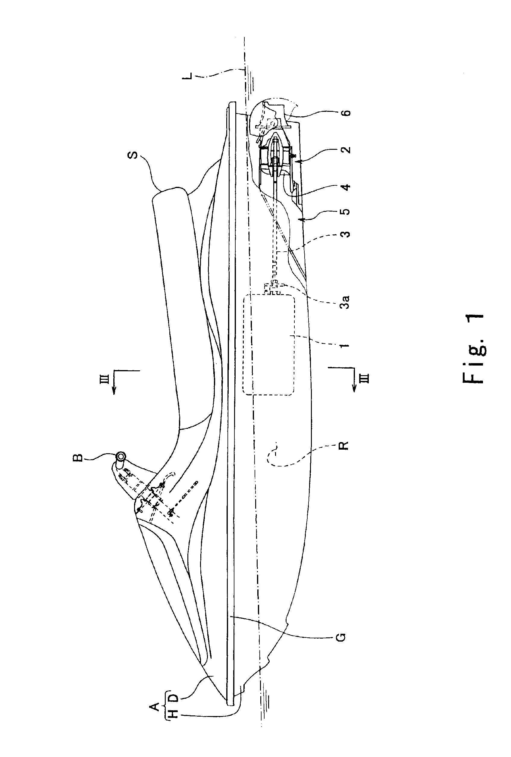
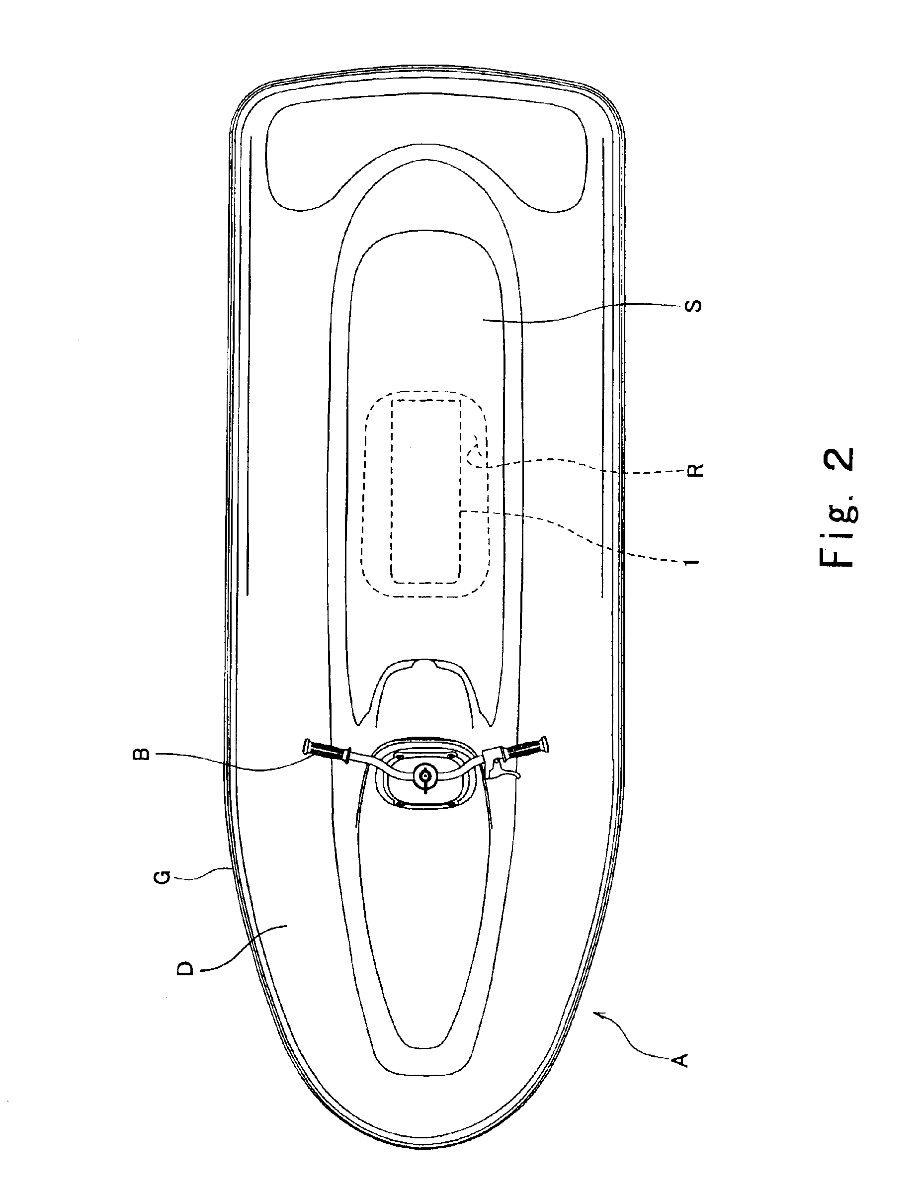
[0055]In FIGS. 1 to 3, reference numeral A denotes a body of the personal watercraft. The body A comprises a hull A and a deck D covering the hull H from above. A line at which the hull H and the deck D are connected over the entire perimeter thereof is called a gunnel line G. L indicates a waterline in a state of the personal watercraft.

[0056]In these Figures, a straddle-type watercraft is shown. The deck D has a raised portion extending substantially from a center portion to a rear portion of the deck D, and a straddle-type seat S is mounted over an upper surface of the raised portion to extend along front-and-rear direction (hereinafter also referred to as longitudinal direction). As used herein, a fore of the watercraft is located on the “front” side and an aft of the watercraft is located on the “rear” side. An engine 1 is disposed in a space (engine ...


PUM


Abstract

Disclosed is a personal watercraft capable of efficiently placing a dry-sump engine room and of efficiently using a dead space in the engine room. The small dry-sump engine comprises: a plurality of cylinders; at least one cylinder head provided as corresponding to the cylinders; a crankcase chamber; an oil tank chamber independent of the crankcase chamber, the oil tank chamber being located lower than the cylinder head; and an oil return passage configured such that its upper end communicates with the cylinder heads and its lower end communicate with the oil tank chamber.

Description


Claims


Application Information

Patent Timeline
Owner KAWASAKI MOTORS LTD
Why Eureka
Try Eureka