No-spill, vapor-recovery, container spout

a technology of spouts and containers, applied in the direction of liquid transferring devices, packaging goods types, liquid handling, etc., can solve the problem of inability to achieve performan

Inactive Publication Date: 2005-05-10
FLORENCE E ALLEN SUCCESSOR TRUSTEE OF THE CLIFFORD H ALLEN TRUST DATED JULY 22 1998
View PDF9 Cites 27 Cited by
  • Summary
  • Abstract
  • Description
  • Claims
  • Application Information

AI Technical Summary

Benefits of technology

[0036]As established by the present invention, a reliable, no-spill, automatic shutoff, vapor-recovery, rapid-flow pouring spout, adaptable to either an un-vented or vented portable fuel container, which prevents the escape of fuel or fuel vapor by sealing the tank opening from the atmosphere and recovering all of the vapor and air mixture displaced by the incoming fuel.

Problems solved by technology

This performance can not be achieved with a conventional vented gas can, because of the lack of a means to quickly stop the flow when the tank is nearly full, and it is not available with the prior-art devices described above without risk of spillage.8. To provide a sealed cushion of trapped vapor and air in the tank after the rising fuel level has reached and covered the entrance to the vapor / air passageway.

Method used


Image

  • No-spill, vapor-recovery, container spout
  • No-spill, vapor-recovery, container spout
  • No-spill, vapor-recovery, container spout

Examples


Embodiment Construction

:—FIGS. 1, 2, 3, 4—PREFERRED EMBODIMENT

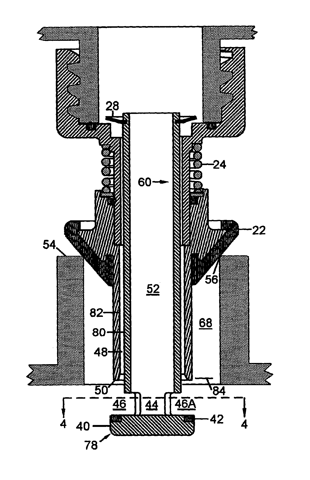
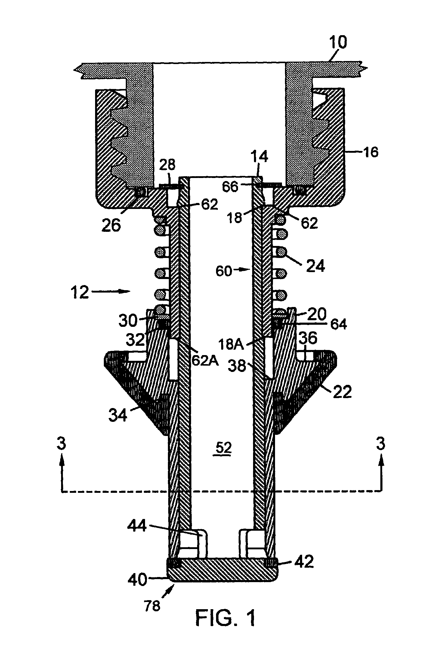
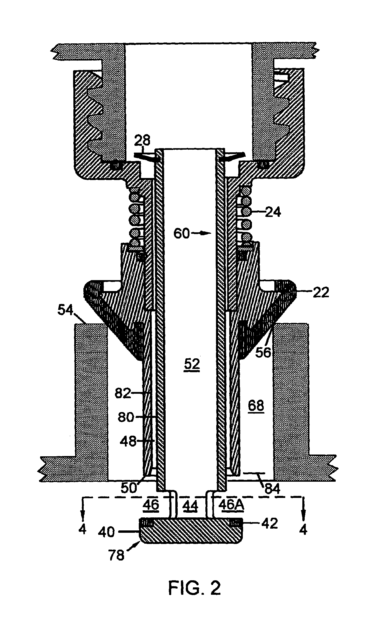
[0043]A preferred embodiment of the spout of the present invention is illustrated in FIG. 1 (valve-closed state) and FIG. 2 (valve-open state) and in cross sectional views FIGS. 3 and 4. Spout 12 includes an intermediate sleeve 16 which is mounted onto a portable container 10 by means of screw threads, and sealed thereto by means of a compressible seal 26. Inner sleeve 14 is fixedly attached to intermediate sleeve 16 by a forced assembly, which causes shoulders 18 and 18A to snap into a locking relationship with mating shoulders 62 and 62A on intermediate sleeve 16 which are closer together by a slight amount than are shoulders 18 and 18A. Inner sleeve 14 and intermediate sleeve 16 thus become and remain a fixed assembly and operate thereafter as if made of one piece. This sub-assembly will hereafter be referred to as assembly 60, which includes a fuel conduit 52 and, at its distal end, provides fluid ports 46 and 46A and valve head 40. It shou...


PUM

PropertyMeasurementUnit
volumeaaaaaaaaaa
included angleaaaaaaaaaa
included cone angleaaaaaaaaaa

Abstract

A vapor recovery spout for a portable fuel container. The spout includes an inner sleeve attached to the container to provide a fuel flow passage through the spout. The passage has an outlet port for fuel to flow through into a tank. A sliding sleeve is mounted on the inner sleeve for sliding axial movement from an outwardly extended position to a retracted position. A radially extending annular seal is mounted on the sliding sleeve for sealing the fuel tank opening when the spout is inserted. Vapor recovery passages are provided between the inner sleeve and the sliding sleeve for displaced vapor to flow from the tank to the container. The sliding sleeve closes the fuel passage and the vapor recovery passageways when in its extended position and opens the fuel passage and the vapor recovery passageways when in its retracted position. A spring urges the sliding sleeve to its extended position.

Description

CROSS-REFERENCE TO RELATED APPLICATIONS[0001]This application claims the benefit of PPA Application No. 60 / 402,582, filed Aug. 12, 2002 by the present inventor.FEDERALLY SPONSORED RESEARCH[0002]Not Applicable.SEQUENCE LISTING OR PROGRAM[0003]Not Applicable.BACKGROUND OF THE INVENTION[0004]1. Field of Invention[0005]This invention relates to spouts for portable gasoline containers which are used to re-fuel off-road power equipment such as tractors, lawn mowers, chainsaws, outboard motors, etc.[0006]2. Background of the Invention[0007]Gasoline spillage while refueling off-road power equipment is a frequent occurrence, and a source of irritation and worry to the operator, since gasoline is highly flammable and explosive. The presence of hot engine components adds to this concern. The problem arises from a combination of poor visibility of the rising fuel level in the vehicle fuel tank, combined with the operator's natural desire to finish the refueling as quickly as possible, while sti...

Claims


Application Information

Patent Timeline
Patent Type & Authority Patents(United States)
IPC IPC(8): B67D5/01B67D7/00
CPCB67D7/005
Inventor ALLEN, CLIFFORD HARRY
Owner FLORENCE E ALLEN SUCCESSOR TRUSTEE OF THE CLIFFORD H ALLEN TRUST DATED JULY 22 1998
Why Eureka
Try Eureka