
Motorized chariot

a motorized chariot and chariot technology, applied in the direction of trailer steering, foldable cycles, braking systems, etc., can solve the problems of unstable vehicles, insufficient maneuverability of vehicles, and difficult control of vehicles

Inactive Publication Date: 2005-05-10
TROLL DONALD E
View PDF33 Cites 63 Cited by
  • Summary
  • Abstract
  • Description
  • Claims
  • Application Information

AI Technical Summary

Benefits of technology

[0005]In a second embodiment, the present invention is a vehicle incorporating a power unit having a front portion and a rear portion. A drive wheel, disposed in the front of the power unit, is connected to a power source. A handle bar extends back from the power unit for steering of the vehicle. This embodiment further includes a trailer unit, having two or more trailer wheels, disposed behind the power unit. Finally, the vehicle incorporates a connecting joint, connecting the power unit to the trailer unit, allowing the power unit and trailer unit to move with respect to one another about two axes.
[0006]In a third embodiment, the present invention is a vehicle including a power unit having a front portion, a rear portion, a power source, and a drive wheel disposed in the front portion of the power unit and connected to the power source. This embodiment incorporates a brake pad, connected to the power unit beneath the power source and a handle bar extending back from the power unit. A trailer unit is disposed behind the power unit, having two trailer wheels, disposed on opposite sides of the trailer unit. A connecting joint, connecting the power unit to the trailer unit, allows the power unit and trailer unit to move with respect to one another about the horizontal pitch axis and vertical yaw axis.

Problems solved by technology

Although certain three-wheeled vehicles have been developed, each of the prior designs incorporates one or more limitations tending to restrict its use in certain applications.
In certain designs, such vehicles are insufficiently maneuverable.
In certain other designs, such vehicles are unstable and difficult to control.

Method used


Image

  • Motorized chariot
  • Motorized chariot
  • Motorized chariot

Examples


Embodiment Construction

[0024]While the making and using of various embodiments of the present invention are discussed in detail below, it should be appreciated that the present invention provides many applicable inventive concepts, which can be embodied in a wide variety of specific contexts. The specific embodiments discussed herein are merely illustrative of specific ways to make and use the invention and do not delimit the scope of the invention.

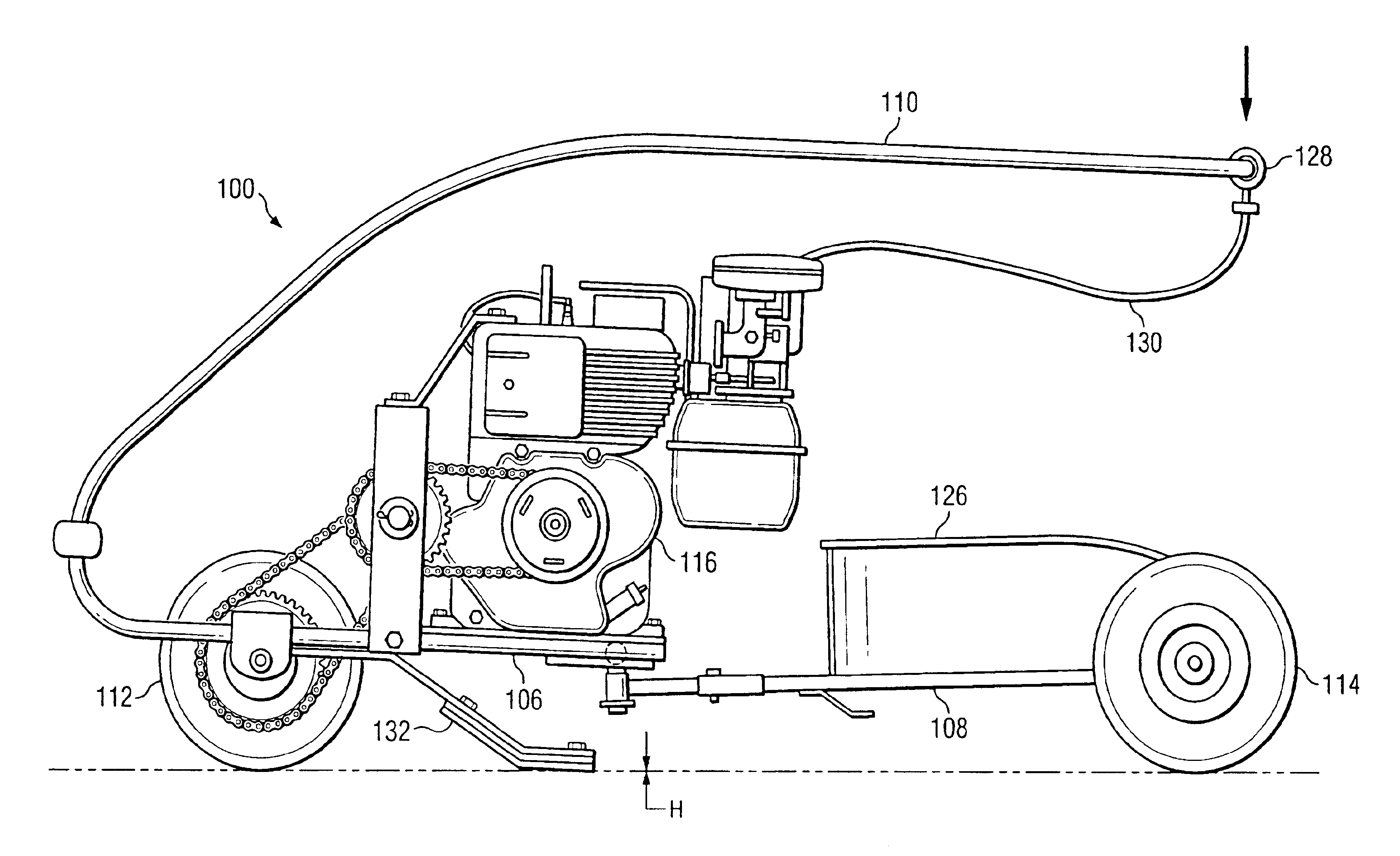
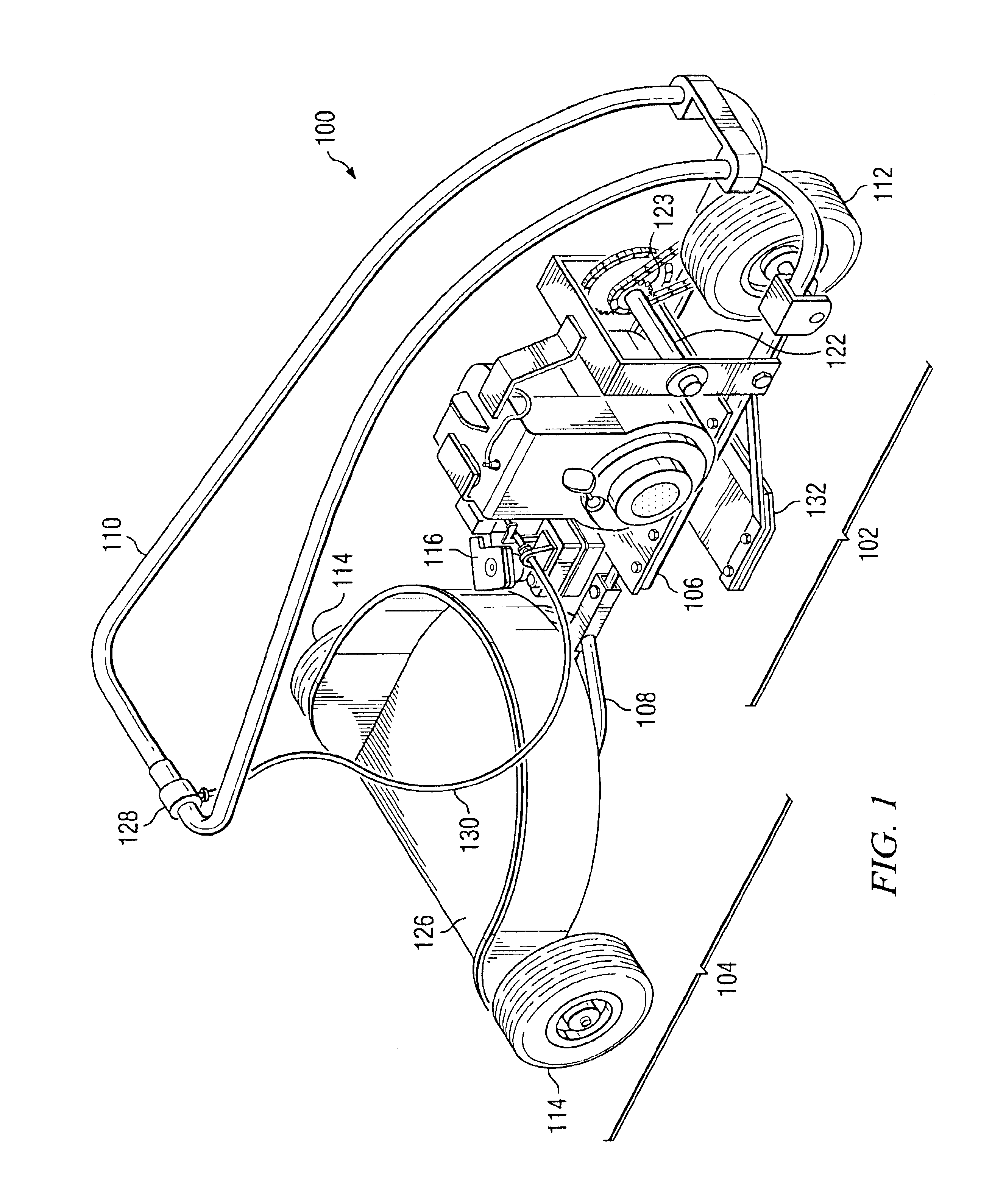
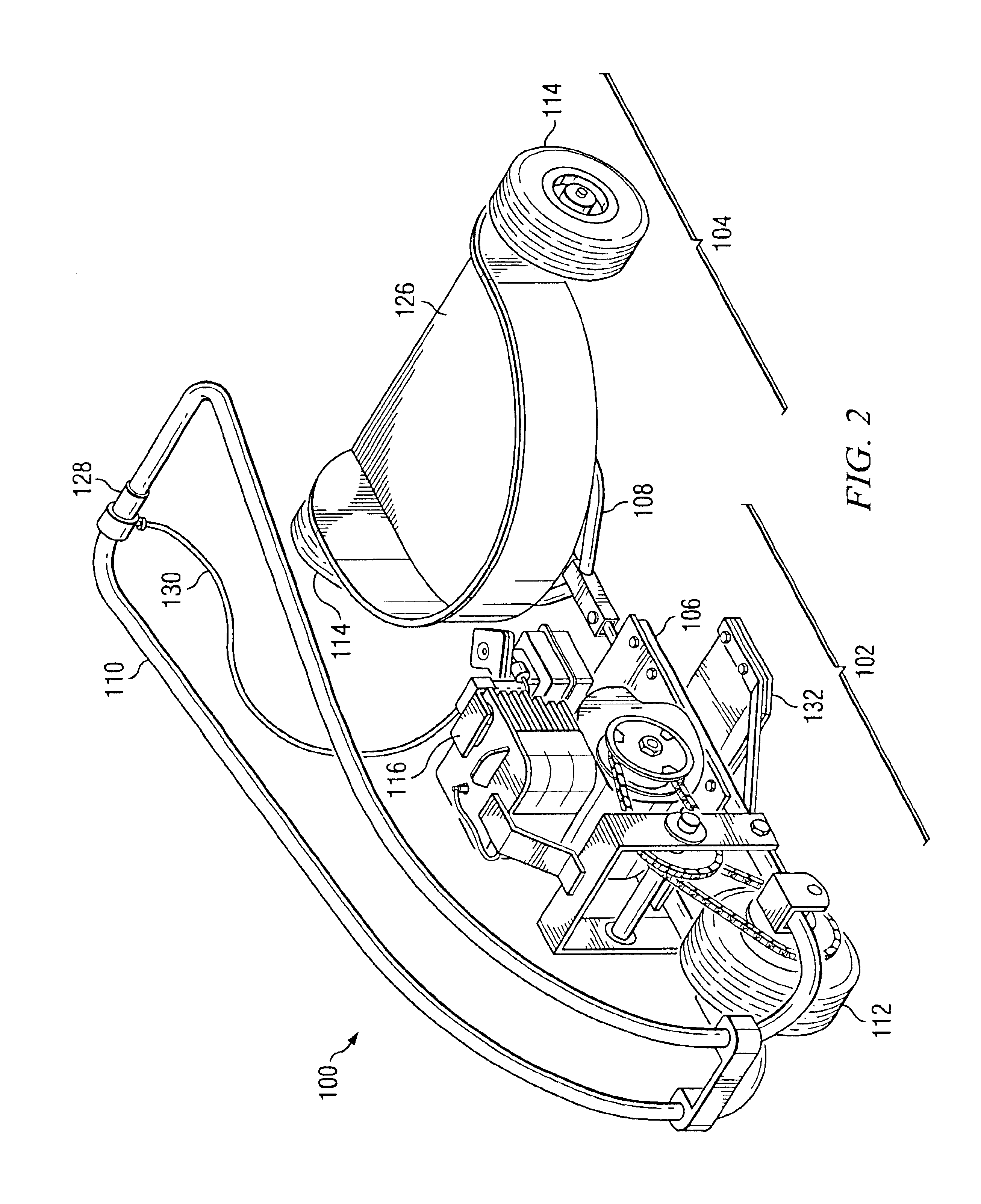
[0025]FIGS. 1 and 2 are isometric views of a motorized chariot 100 in accordance with one embodiment of the present invention. FIGS. 3, 4 and 5 are side views of the motorized chariot 100 of FIGS. 1 and 2. FIG. 6 is a top view of the motorized chariot 100 of FIGS. 1-5.

[0026]As seen in FIGS. 1-6, motorized chariot 100 incorporates a power unit 102 disposed ahead of, and connected to, a trailer unit 104, so as to pull trailer unit 104. Power unit 102 and trailer unit 104 are built around a power unit frame 106 and trailer unit frame 108, respectively. The directi...


PUM


Abstract

A vehicle incorporating a power unit having a front portion, a rear portion and a power source. A drive wheel, disposed in the front of the power unit, is connected to the power source. A brake pad is connected to the power unit beneath the power source and a handle bar extends back from the power unit. The vehicle includes a trailer unit, disposed behind the power unit, having two trailer wheels, disposed on opposite sides of the trailer unit. A connecting joint, connecting the power unit to the trailer unit, allows the power unit and trailer unit to move with respect to one another about the horizontal pitch axis and / or vertical yaw axis.

Description

FIELD OF THE INVENTION[0001]The present invention relates generally to motorized vehicles, and more specifically to a motorized vehicle having a separate power unit and trailer unit.BACKGROUND OF THE INVENTION[0002]A variety of wheeled vehicles are known. Three-wheeled powered vehicles are not new. A number of designs and configurations of wheeled vehicles have been developed for use in a broad range of applications. Certain such designs have a unitary construction, while other designs have used a construction having more than one segment, wherein the multiple segments are articulated to one another through some form of joint or joints.[0003]Although certain three-wheeled vehicles have been developed, each of the prior designs incorporates one or more limitations tending to restrict its use in certain applications. In certain designs, such vehicles are insufficiently maneuverable. In certain other designs, such vehicles are unstable and difficult to control. There remains in the fie...

Claims


Application Information

Patent Timeline
IPC IPC(8): B62D51/02B62D51/00B62D61/08B62D61/00
CPCB62D61/08B62D51/02
Inventor TROLL, DONALD E.
Owner TROLL DONALD E
Learn More