Inserta clamp

a clamping device and inserting technology, applied in the direction of positioning apparatus, metal-working machine components, manufacturing tools, etc., can solve the problems of time-consuming and inconvenient way to get the job done, out of the reach of the clamping arm and the clamping pad, and inconvenient to do, so as to expand the functionality and flexibility of the clamping device. , the effect of easy removal

Inactive Publication Date: 2005-05-10
VALTRA
View PDF19 Cites 46 Cited by
  • Summary
  • Abstract
  • Description
  • Claims
  • Application Information

AI Technical Summary

Benefits of technology

[0007]It is the intention of the present invention to provide a clamping device to hold a workpiece tightly, quickly and conveniently anywhere on the working surface of a table, a workbench, or a machine tool regardless of the size of the workpiece and the working surface. Another intention is to enable the present invention to clamp a workpiece anywhere on the working surface without the use of clamping bars, beams or fixtures. Yet another intention of the present invention is to enable the clamping of a workpiece against the working surface without crossing over the edge and reaching the bottom of the work table, workbench or machine tool. It is also the intention of the present invention to lock itself on the working surface by means which can be applied and removed on the top surface only, so there is no need to work underneath the work table, workbench or machine tool. Another intention of the present invention is to make a clamping device, which can be used on various types of working surfaces, such as wood, metal or machine tool, and yet it can be relocated easily over the surface. A further intention of the present invention is to expand the functionality and flexibility of a clamping device by adding a quick release button to the shank, a cylindrical mounting base and a Y-axis attachment.
[0009]To clamp a workpiece on a working surface, the straight shank with the short cylindrical sleeve is attached to the surface and then the movable arm is moved up or down along the shank to a proper location so that the threaded rod can be lowered to clamp the workpiece with the clamping pad. For machine tool applications, the short cylindrical sleeve at the bottom of the shank is inserted into one of the tooling holes on the working surface of the machine tool. If the size of the tooling hole is too big for the cylindrical sleeve, a sleeve of the right size will be used between the and the hole. When pressure is applied to the workpiece through the movable arm and the clamping pad, the shank is tilted a little bit so that the short cylindrical sleeve is skewed against the wall of the tooling hole and the friction created will be sufficient to hold the workpiece against the working surface. For those working surfaces without tooling holes, the short cylindrical sleeve of the straight shank is inserted to the cylindrical mounting base, which is mounted on the working surface with screws. The same method can be used on wooden work tables or workbenchs too. To use the present invention on metal surfaces other than a machine tool, the cylindrical mounting base can also be used as described above. Besides that, a short cylindrical metal tube with an internal diameter a little bit bigger than the external diameter of the short cylindrical sleeve of the shank is spot welded on the metal surface where clamping is required. Then the short cylindrical sleeve of the shank is inserted into the short cylindrical tube and the workpiece can be clamped as mentioned above. To relocate or remove the present invention after the work is finished, the clamping pad is released from the workpiece and hence the friction between the short cylindrical sleeve and the short cylindrical tube is reduced too. Then the present invention can be removed from the working surface. The short cylindrical tube can easily be removed by breaking the spot weld with a hammer, or striking it or prying it with a metal rod. Then the metal surface can be polished to remove the spot weld residue with a suitable power hand tool. Multiple multi-function clamps can be used together at different tooling holes of the said working surface for workpieces of various shapes and sizes.
[0010]A Y-axis attachment is devised to enhance the functionality and flexibility of the present invention. It comprises two rectangular metal plates with an elongated hole in the middle, which metal plates are spaced apart by cylindrical blocks at each end. A rectangular block fits inside of, but is free to move between the two metal plates. Two threaded rods are provided. One rod feeds through one of the cylindrical blocks, and the other rod feeds through the other cylindrical block. The rectangular block is equipped with a rectangular hole in the middle. The size of the hole is a bit bigger than the cross-section of the straight shank so that the shank can be fed through it freely. A screw hole is provided on one side of the rectangular block to accept a screw to secure the position of the rectangular block to the shank so that the Y-axis attachment will not move or drop along the shank. The shorter one of the threaded rods in the cylindrical blocks is attached to a clamping pad while the longer one of the threaded rods is equipped with a turning handle. The longer threaded rod is left-hand threaded and the free end of it is pivoted to the rectangular block. Hence turning the longer threaded rod clockwise with the turning handle will advance the Y-axis attachment towards the clamping pad end or the workpiece and turning it counterclockwise will retract the assembly away from the workpiece. With the Y-axis attachment slid over the shank of the present invention, it is possible to clamp a second workpiece along an axis perpendicular to the clamping direction of the first workpiece.
[0011]To facilitate the easy insertion and removal of the Y-axis attachment and the movable arm from the straight shank, a quick release button is equipped at the upper end of the shank. It is a metal push button with a loaded compression spring inside. Normally, it prevents the movable arm and the Y-axis attachment from dropping off the shank and when it is pressed, the insertion and removal of these items will be very easy.

Problems solved by technology

However, when the workpiece and the workbench are relatively large, the middle part of the workpiece will be out of the reach of the clamping arms and clamping pads.
This is a logical way to solve the problem, but it is also a very time consuming and inconvenient way to get the job done.
When the workpiece and the workbench are relatively large, it would be very inconvenient to do so.
The only inconvenience is to prepare threaded holes or holes with nuts underneath the bench top for the clamping bolt.

Method used


Image

  • Inserta clamp
  • Inserta clamp
  • Inserta clamp

Examples


Embodiment Construction

[0016]With the help of the drawings and the detail description below, the features of the present invention will be apparent and fully understandable.

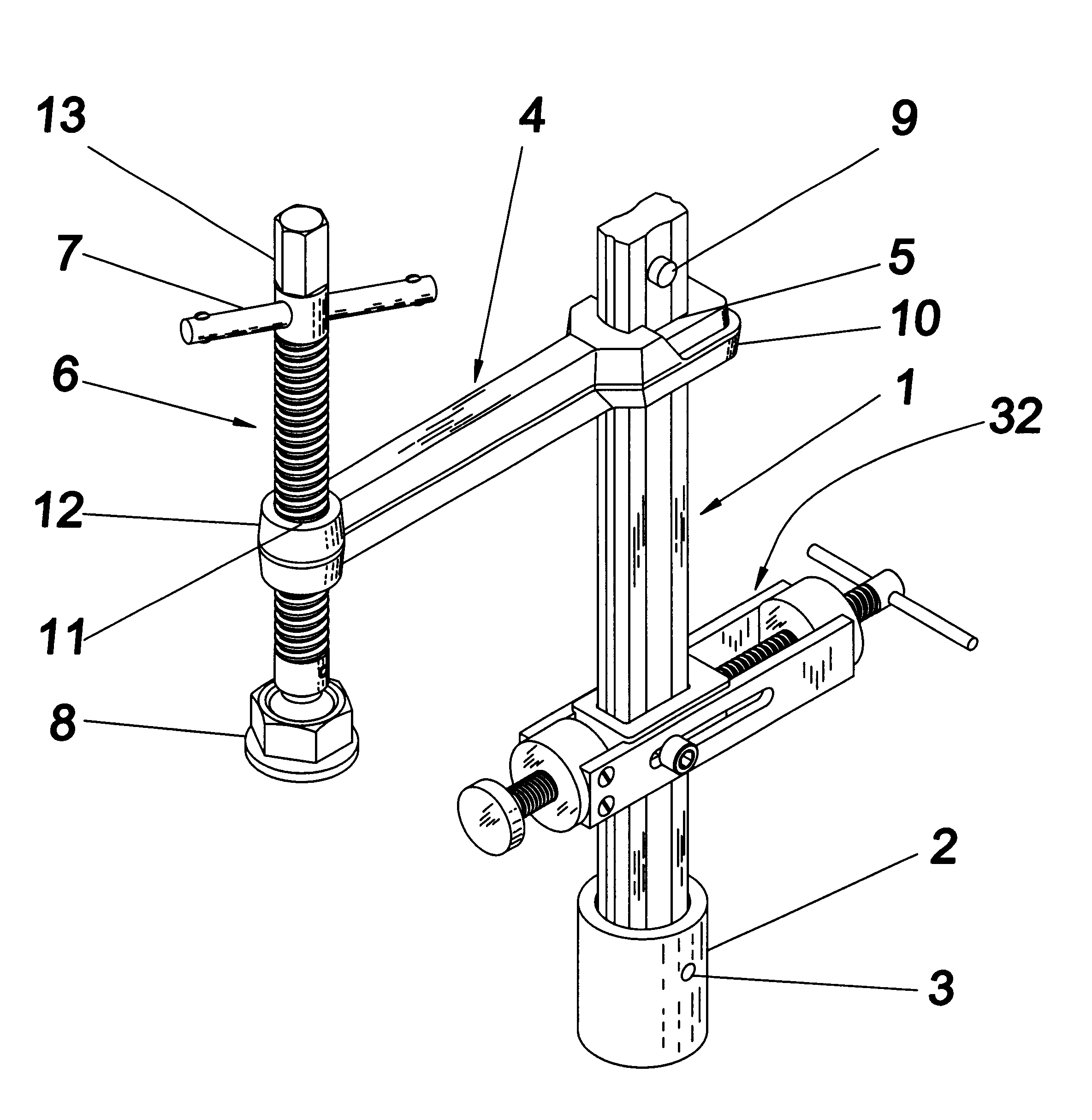
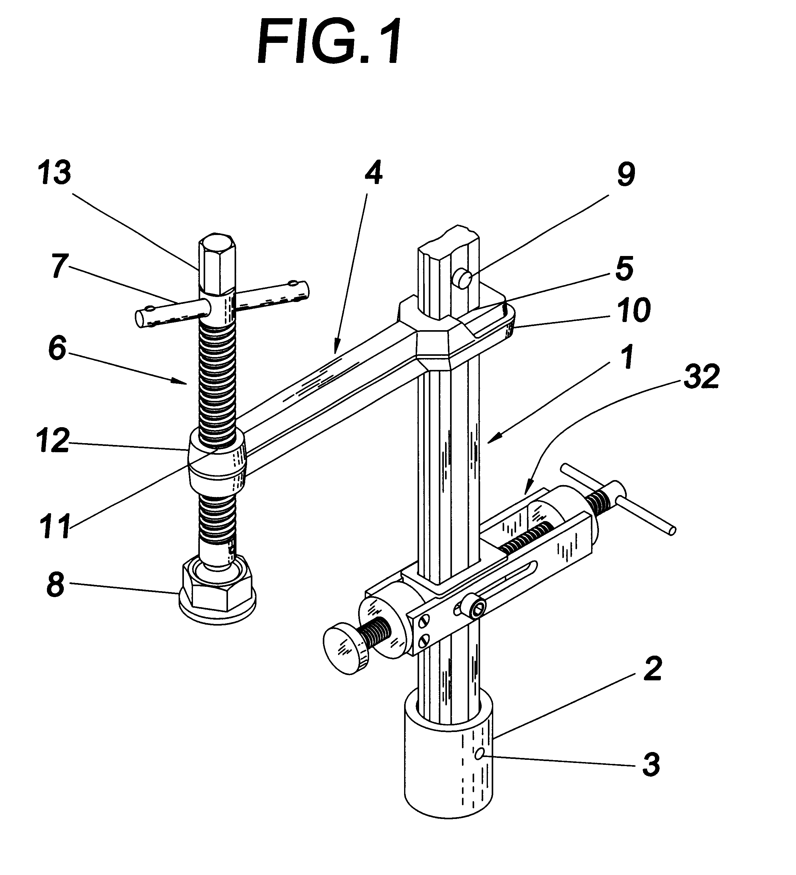
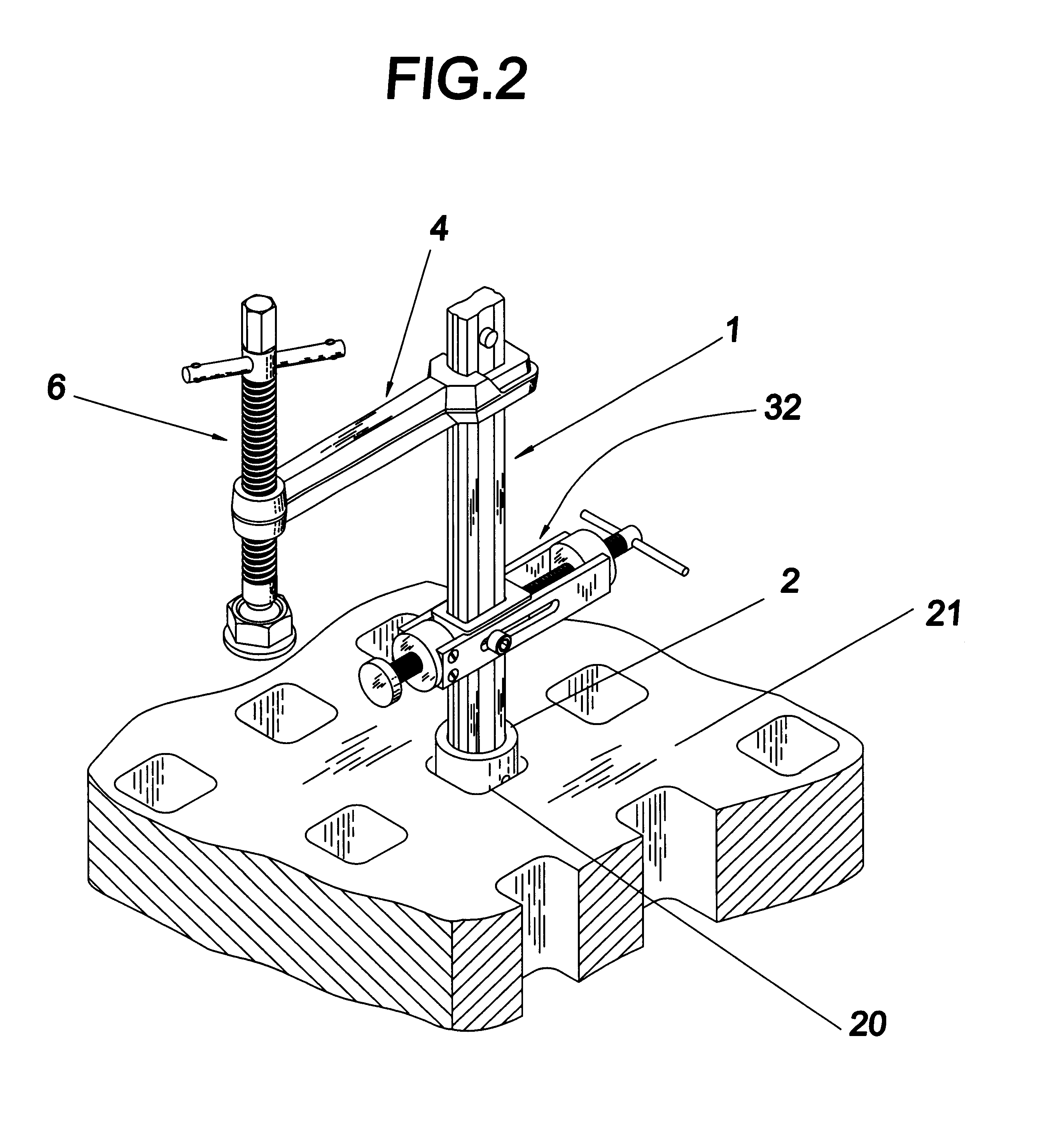
[0017]Referring to FIG. 1, the present invention, a multi-function clamp, comprises a straight shank 1, a short cylindrical sleeve 2 attached and fixed to the lower end of shank 1 by taper pin 3, and a movable arm 4 with one end slid over the top end of shank 1 through rectangular hole 5, and the other end fitted with a threaded rod 6, turning handle 7, and the clamping pad 8. The straight shank 1 acts as the fixed arm of a conventional clamp. At the upper end of shank 1, a spring loaded quick release button 9 is equipped to prevent the falling off of the movable arm 4 and other attachments from shank 1, but at the same time it allows quick and easy insertion of these items onto shank 1. Movable arm 4 is a metal bar with a rectangular hole 5 at one end 10 and a cylindrical threaded hole 11 at the other end 12. The upper end of shank 1 ...


PUM

PropertyMeasurementUnit
flexibilityaaaaaaaaaa
angleaaaaaaaaaa
diameteraaaaaaaaaa

Abstract

The present invention relates to a general purpose clamping device. It comprises a straight shank with the lower end attached to a short cylindrical sleeve and a movable arm sliding over the shank. Feeding through the free end of the movable arm is a threaded rod with clamping pad and turning handle at the lower end and upper end respectively. The present invention is designed to hold a workpiece tightly, quickly and conveniently on the working surface of a table, workbench or machine tool. And the invention can be relocated easily over the workbench made of wood or metal, or over the working surface of a machine tool. Attachments are provided to enhance the functionality of the invention. A Y-axis attachment assembly is adapted to being slidably mounted on the straight shank to hold a second workpiece along an axis that is generally perpendicular to the vertical clamping direction of the multi-function clamp.

Description

BACKGROUND OF THE INVENTION[0001]1. Field of the Invention[0002]The present invention relates to a general purpose clamping device and more particularly to a multi-function clamp. The invention is designed to hold a workpiece tightly, quickly and conveniently on the working surface of a table, a workbench, or a machine tool. Yet the invention can be relocated easily for different configurations and can be removed without trouble after the work is finished. The working surface of the table or workbench can be made of wood or metal, whereas the working surface of a machine tool is a metal surface with or without tooling holes.[0003]The present invention comprises a straight shank with the lower end attached to a short cylindrical sleeve and a movable arm sliding over the shank. Feeding through the free end of the movable arm is a threaded rod with a clamping pad at the lower end and a turning handle at the upper end. Attachments of various designs, including a cylindrical mounting bas...

Claims


Application Information

Patent Timeline
Patent Type & Authority Patents(United States)
IPC IPC(8): B23Q3/06
CPCB23Q3/069Y10T29/53909
Inventor WONG, HARRY
Owner VALTRA
Why Eureka
Try Eureka