CT gantry balance system

a gantry and gantry technology, applied in the field of ct systems, can solve the problems of generating artifacts and affecting the quality of images, and achieve the effects of reducing guesswork, accurate balancing, and facilitating field adjustmen

Inactive Publication Date: 2005-05-10
GE MEDICAL SYST GLOBAL TECH CO LLC
View PDF6 Cites 21 Cited by
  • Summary
  • Abstract
  • Description
  • Claims
  • Application Information

AI Technical Summary

Benefits of technology

[0005]The present invention comprises an improved method and system for balancing of CT gantry mechanisms, both in the factory and in the field. With the present invention, CT gantry mechanisms can be both statically and dynamically balanced, even in field situations. With the present method, both static and dynamic imbalance can be measured and, if necessary, eliminated. The present invention results in reduction in time and complexity for the user compared with existing CT static balancing methods.
[0010]With the present invention, static and dynamic balancing of the rotating base members of CT gantry systems can be provided, both in the factory and in the field. Also, specific instructions to the user are provided with the present system in order to eliminate guess work and provide accurate balancing. Having just two locations for balance weights rather than numerous sites is also a benefit and provides for easier adjustment in the field. Finally, with the present invention, a finite number and types of balance weights are needed.

Problems solved by technology

This motion is detrimental to the quality of the images and can generate artifacts when the motion is increased above a certain threshold.

Method used


Image

  • CT gantry balance system
  • CT gantry balance system
  • CT gantry balance system

Examples


Embodiment Construction

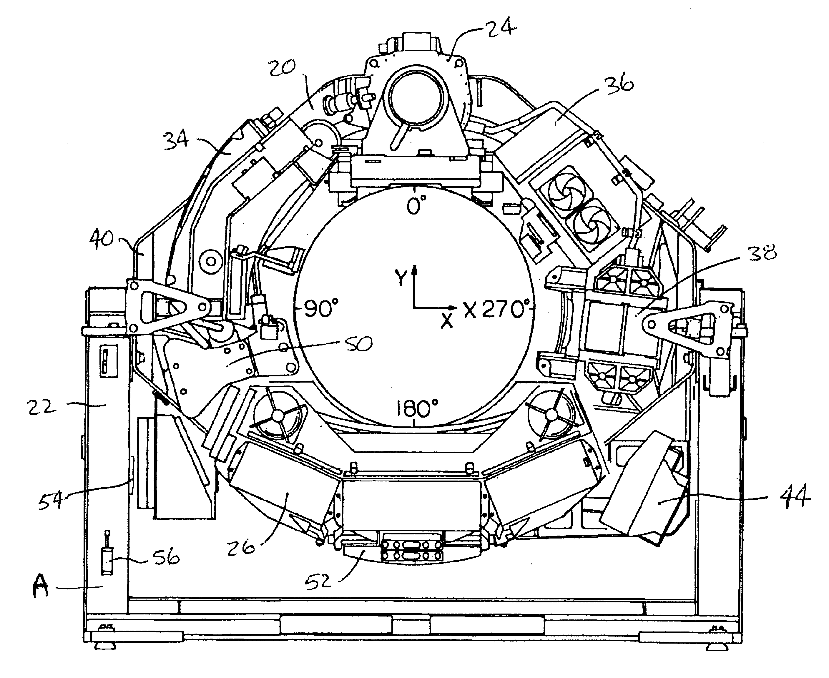
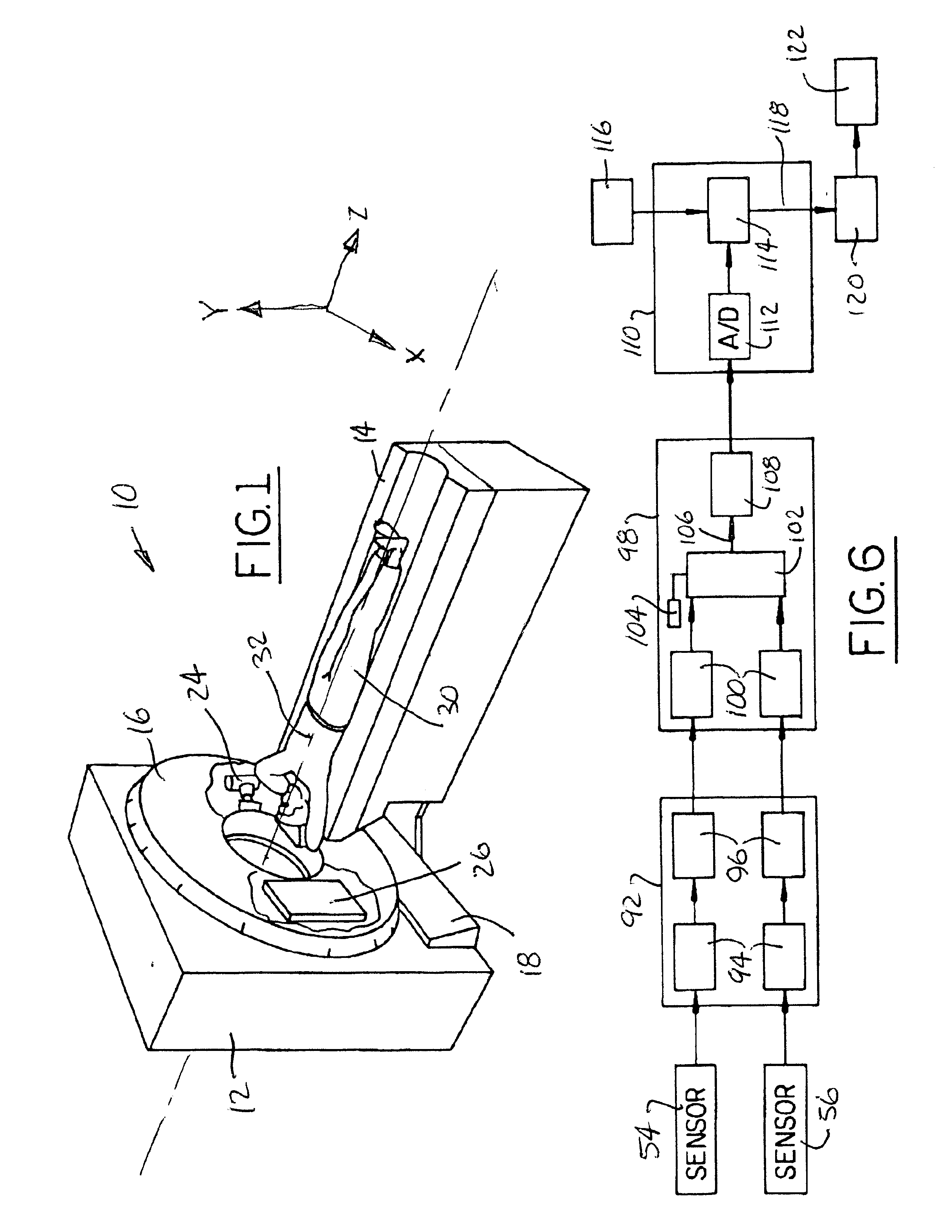
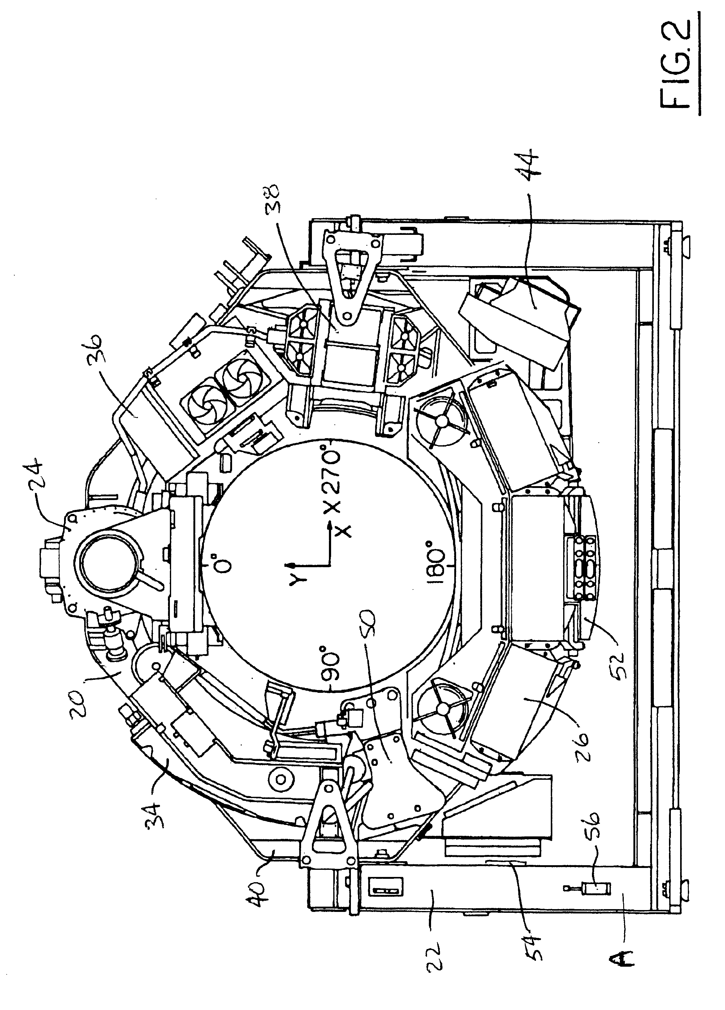
[0019]A conventional CT system is shown in FIG. 1 and referred to generally by the reference numeral 10. The CT system includes a gantry member 12 and a patient table member 14. The gantry member 12 includes an annular portion 16 and a base portion 18. A rotating base member 20, as shown in FIGS. 2-5, is positioned inside the annular portion 16, while a stationary base member 22 is positioned inside the base member 18.

[0020]In accordance with standard CT systems, an x-ray tube and collimator 24 is positioned on the rotating base member 20 together with a detector plate member 26. A patient 30 or other object is positioned on the table member 14 and moved along the Z-axis 32 which is the axis of rotation of the rotating base member 20 and gantry member 12. The x-ray tube member 24 and detector plate member 26 are positioned opposite one another on the gantry member and x-ray images of the patient 30 or object on the table member 14 are made as the table member moves through the centr...


PUM


Abstract

A method and system for balancing CT gantry mechanisms. Two balance locations are preselected on the rotating base member and stacks of spacers, shims, and weights are provided at each site. Strain gate sensors are provided on the stationary base member and included as part of a sensor circuit. Trial and test runs determine the mass and Z-location of the mass which needs to be added to the system to statically and dynamically balance it.

Description

BACKGROUND OF INVENTION[0001]The present invention relates to CT systems and more particularly to methods and systems for balancing CT gantry members.[0002]Computed Tomography (“CT”) systems are in wide use today. The CT systems take X-ray images of objects or persons in order to provide scientific and / or medical information. In general, CT systems include a large gantry mechanism positioned in a housing with an annular opening in which the object or person is positioned. The gantry mechanism includes a rotating base member on which an X-ray tube and detector plate are mounted. As the base member rotates and the object or person is moved along the axis of rotation, X-ray images are taken for later analysis.[0003]The rotating base member typically has other system components mounted on it, such as a heat exchanger and generator. The X-ray tube, detector plate, and other components rotate with the base member. It is important to balance the rotating base member so that it revolves uni...

Claims


Application Information

Patent Timeline
Patent Type & Authority Patents(United States)
IPC IPC(8): A61B6/03G01M1/32
CPCG01M1/32A61B6/035
Inventor REZNICEK, MARK EDMUNDPLATE, ERIC MATTHEWFAESSLER, SHAWN PATRICK
Owner GE MEDICAL SYST GLOBAL TECH CO LLC
Why Eureka
Try Eureka