

Connector holding structure
- Summary
- Abstract
- Description
- Claims
- Application Information
AI Technical Summary
Benefits of technology
Problems solved by technology
Method used
Image

Examples
first embodiment
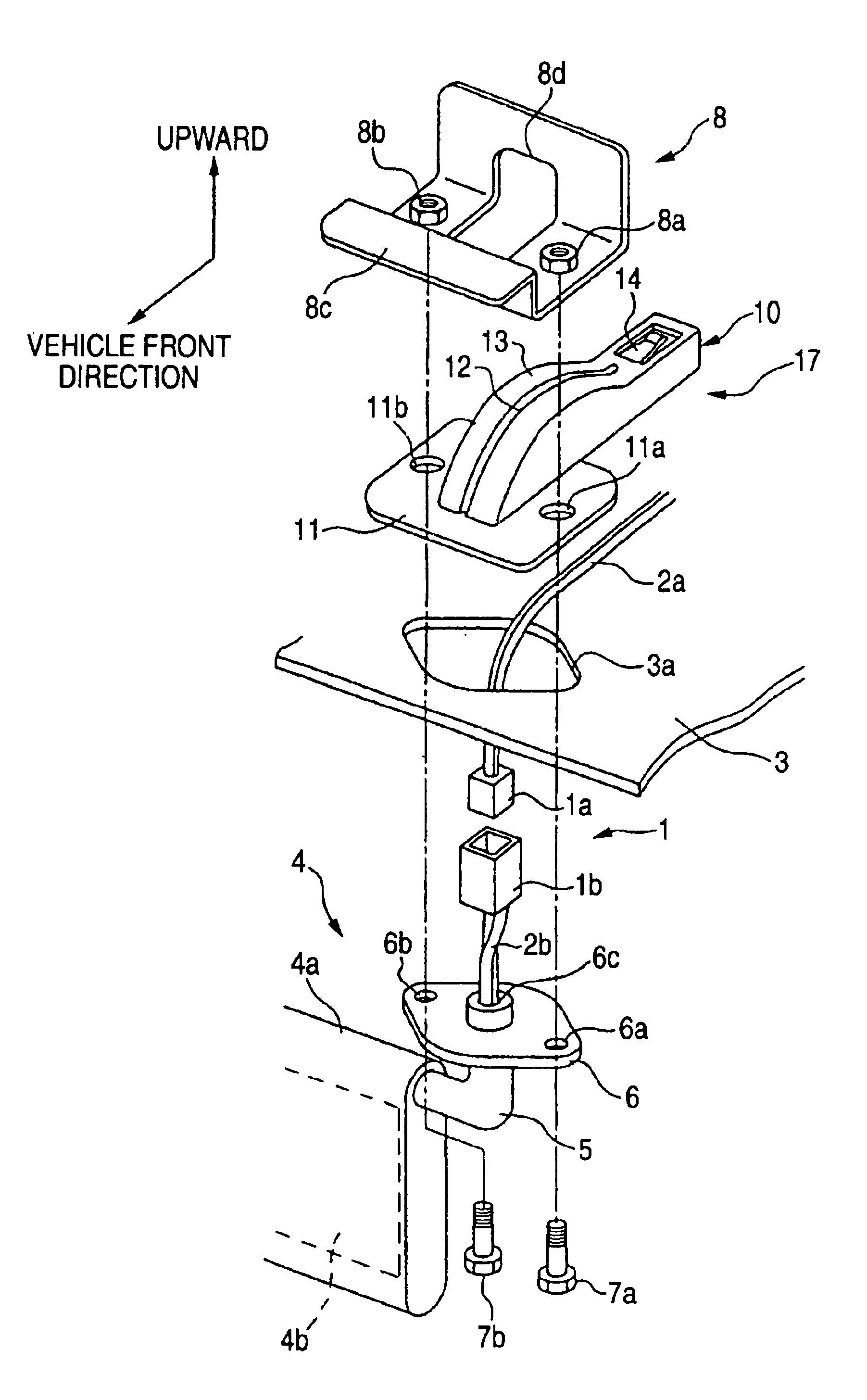
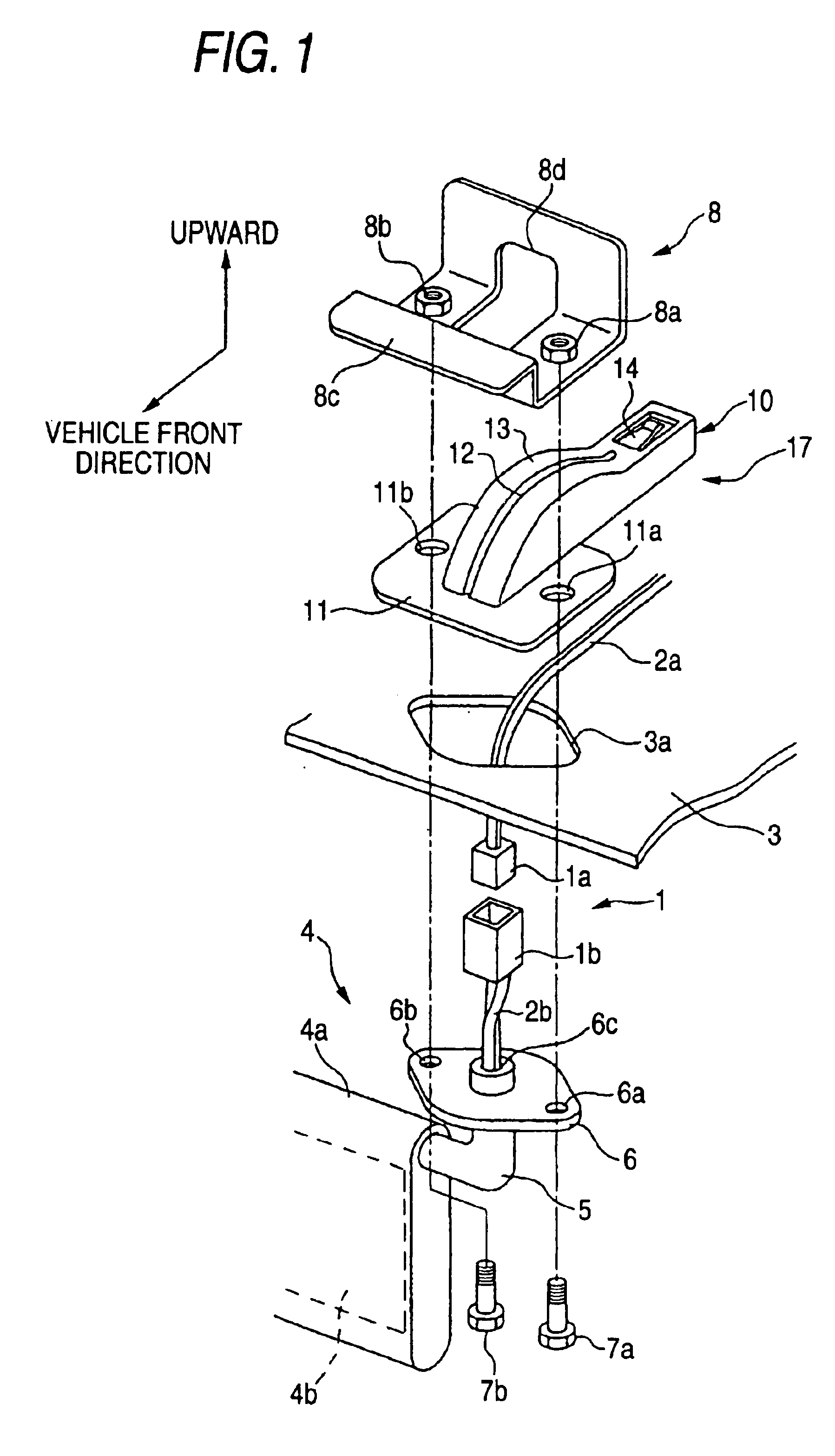
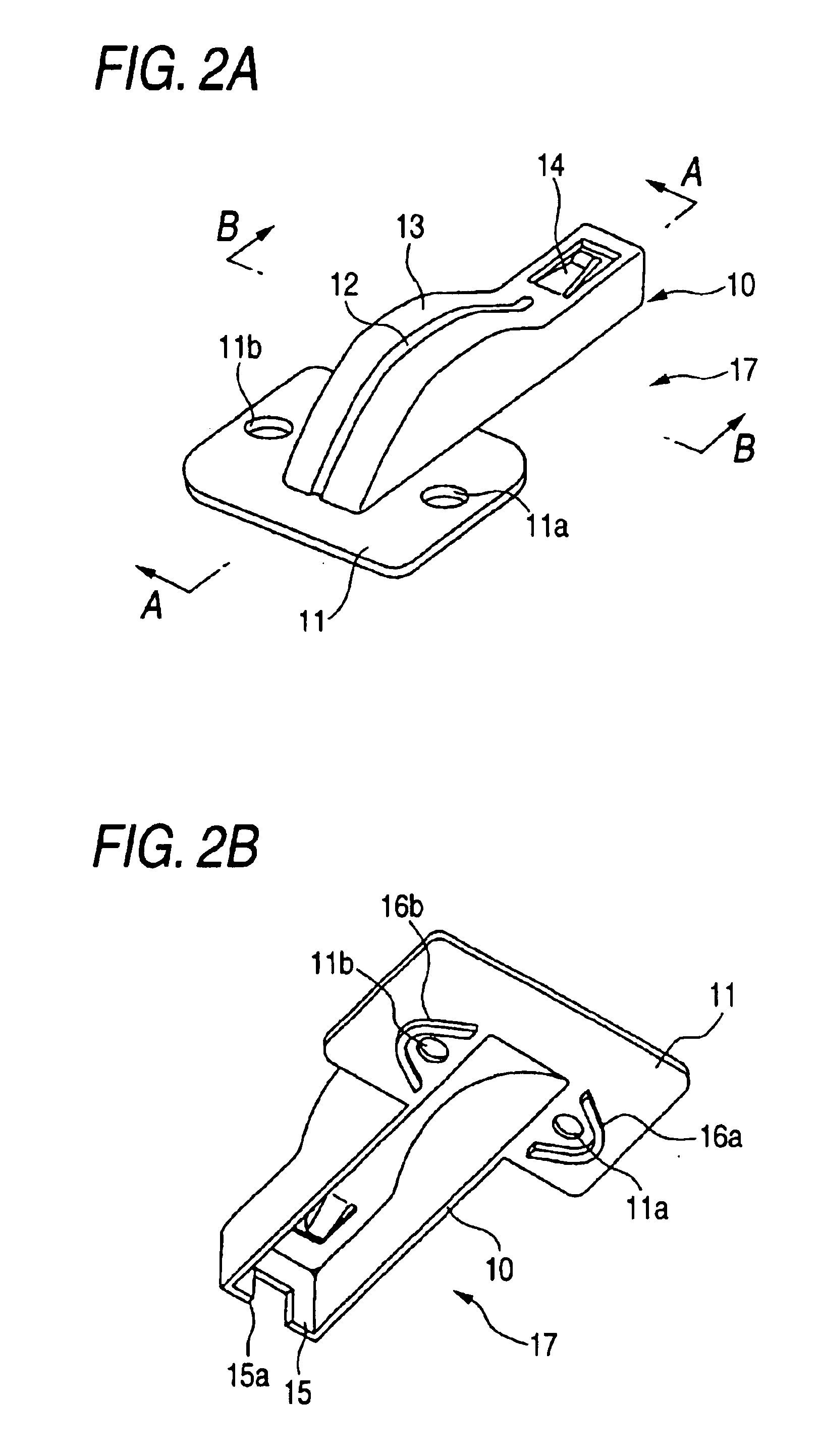
[0067]FIGS. 1 to 7B show a sun visor attaching structure, in which a connector holding structure of the first embodiment is applied to a sun visor serving as an interior part. FIG. 1 is a schematic exploded perspective view thereof. FIGS. 2A and 2B schematically show an accommodating mechanism thereof. FIGS. 3A and 3B show a sectional shape of the accommodating mechanism thereof. FIG. 3A is a sectional view taken along line A—A of FIG. 2A. FIG. 3B is a sectional view of taken along line B—B of FIG. 2A. FIG. 4 is a sectional view in a state in which a connector is pushed into the inside of the accommodating mechanism. In FIGS. 1 to 4, like reference characters designate like parts of the aforementioned conventional sun visor attaching structure.
[0068]In FIG. 1, reference numeral 4 denotes a sun visor, reference numeral 3 denotes a headlining, reference numeral 10 denotes a connector fixing cover (or cover body) serving as an accommodating body, reference numeral 8 denotes a body brac...
second embodiment
[0129]The sun visor attaching structure, to which the connector holding structure as the invention is applied, is configured as described above. The procedure for attaching the sun visor 4 to the headlining 3 is described below.
[0130]An adhesive agent is applied to the bottom surface of the fixing portion 23 of the guide body 20. The guide body 20 is fixed to the top surface of the headlining 3 in a state in which the positioning portion 24 of the guide body 20 is engaged with the edge portion of the attaching hole 3a of the headlining 3.
[0131]Furthermore, the harnesses 2a pass through the top surface of the slide member 30 and between each of both side portions of the guide body 20. Then, the projecting piece 32 provided at the front end of the slide member 30 is latched to the latching portion 9 of the subconnector 1a, so that the subconnector 1a is fixed to the slide member 30.
[0132]Thereafter, in the cutout portion 31 of the slide member 30, the harnesses 2a are fixed to the sli...
PUM
 Abstract
Description
Claims
Application Information