
Vessel valve

Inactive Publication Date: 2005-05-10
JCL TECHNIC
View PDF10 Cites 49 Cited by
  • Summary
  • Abstract
  • Description
  • Claims
  • Application Information

AI Technical Summary

Benefits of technology

[0007]The present invention has for an object to provide a cardiac valve by which the prior art disadvantages are eliminated or at any rate essentially reduced.
[0009]Yet another object of the invention is to provide a valve where the flap elements in open position define a unitary flow passage for the blood, whereby flow outside of the backside of the valve elements is substantially avoided.
[0015]For the purpose of reducing the flow of blood on the outside of the flap elements when in open position it is preferred that the distance between the semi-spheres corresponds to a sector angle of about 10 to about 20°.

Problems solved by technology

The designs not based on natural tissue are all made as more or less complicated constructions which result in risk of failure or unsatisfactory function in other ways.
Many of the known valves are furthermore designed in an asymmetric way with concomitant inconveniences.
Finally, it can be mentioned that known valves often are associated with inertia in their opening or closing movement which substantially reduces their efficiency.
This construction results in the disadvantage that an asymmetric flow pattern is created with concomitant turbulence and undesired deposits.
One part of the hinge arrangement is constituted by a yoke directed inwardly into the flow of blood, whereby disturbances arise in the flow of blood and thereby non-desired deposits of coagulated blood.
Furthermore, the construction means that in the open state spaces are formed between the exterior surface of the valve elements and the interior surface of the ring through which blood can flow at the side of the main flow, and also this condition results in non-desired flow profiles creating conditions for deposits in an undesired way.
The disadvantage of this known construction is that these pins or studs are arranged in a through-hole in the ring whereby blood can enter into these holes both from the inside and from the outside.
Since such blood present around the pin is stationary and not continually replaced problems arise in the form of deposits of coagulated blood and thereby associated problems.

Method used


Image

  • Vessel valve
  • Vessel valve
  • Vessel valve

Examples


Embodiment Construction

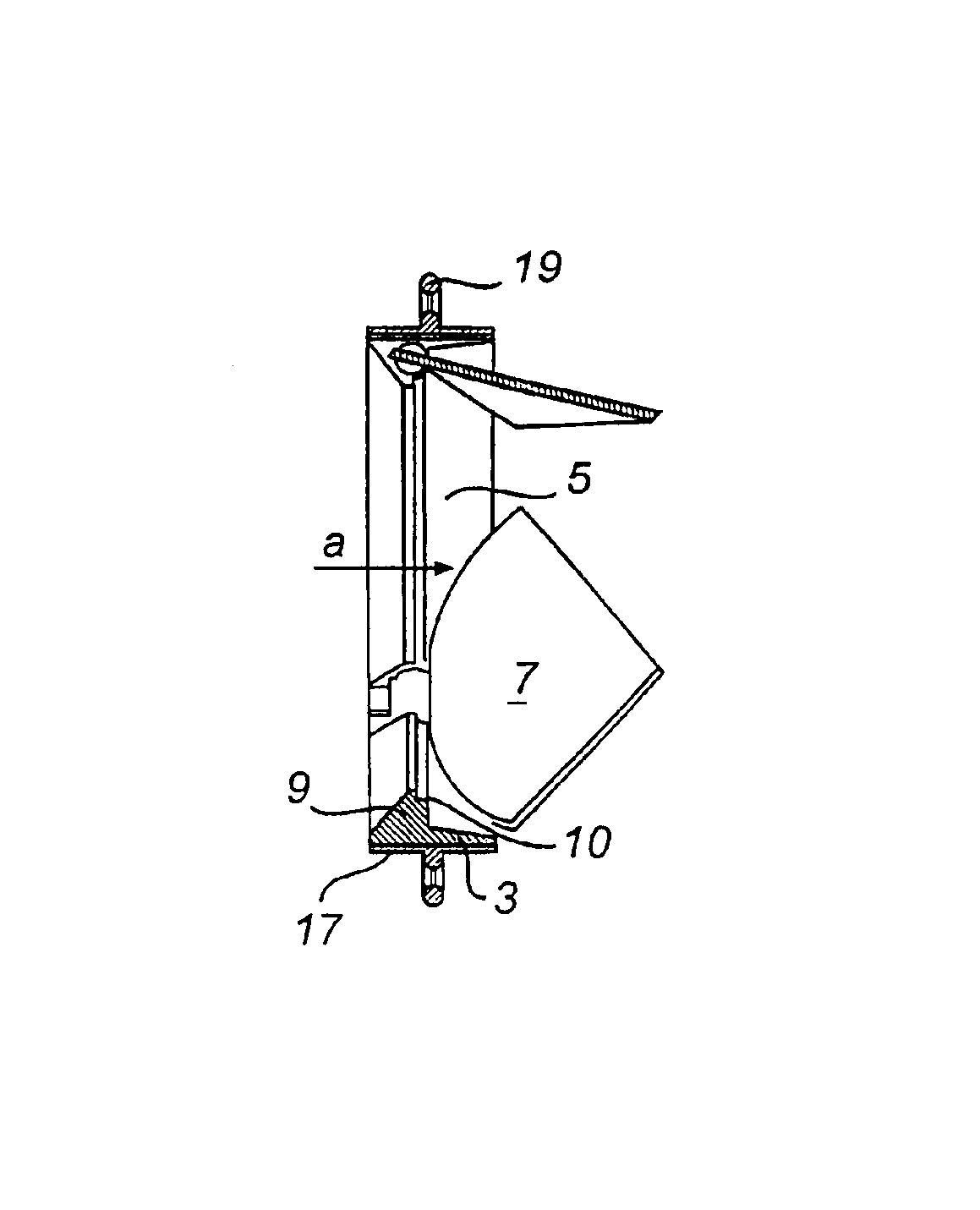
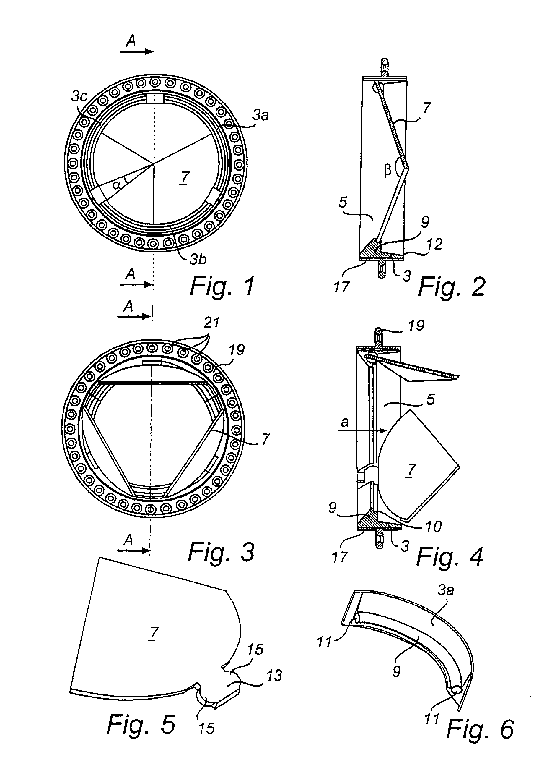
[0026]The embodiment shown in the drawing is particularly useful for use as a cardiac valve or so called heart valve and is shown in a scale of about 2:1. The cardiac valve consists in principle of a sleeve or ring 3 having a central passage 5, through which blood can pass the valve in the direction of arrow a with the valve in open position (FIG. 4). The ring 3 is composed of three sections 3a, 3b, 3c, one being shown in perspective in FIG. 6, and these three sections are attached to each other in a suitable manner, for example by welding with the valve made of a biocompatible metal, for example stainless steel or titanium.

[0027]The sleeve or ring 3 is provided with a radially inwardly directed circular flange 9, three flap elements 7 being pivotably connected in a manner to be described further below.

[0028]Thus, ring 3 contains three flap elements 7, of which each is designed as a circle segment as seen in the plan of the paper, where the sector angle α thus is 120°. In a closed p...


PUM


Abstract

A vessel valve including a sleeve or ring having a central opening and openable and closeable flap elements intended to allow the flow of blood through the central opening in one direction, whereas the flap elements are designed as circle segments, and the sector angle is 360⁢°nwherein n is a number of circle segments and is equal to 3, 4, 5 or 6, and wherein each flap element at its outer edge is pivotably connected to an inwardly directed flange on the inside of the ring so that in a closed position they co-operate to form a sealing body and in an open position they allow free passage of blood. The ring is composed of n sections, whose pair-wise juxtaposed ends form recesses in the flange accommodating hinge elements which are arranged in the middle of the outer edge of each of the flap elements and which with assembled sections are locked by undercutting; and a method for the manufacture of such vessel valve.

Description

TECHNICAL FIELD[0001]The present invention relates to implantable back valves to be placed in vessels of living creatures including man. The invention is particularly related to so called cardiac valves, in other words heart valves, intended to allow flow of blood in one direction in a blood path in connection to the heart of a living mammal, comprising man. Even if the invention is not restricted hereto it will be described in the following mainly in connection with cardiac valves, so called heart valves.BACKGROUND OF THE INVENTION[0002]Cardiac valves, so called heart valves, are found in a number of embodiments made both of wholly artificial materials, such as titanium, pyrolytic carbon or the like, or manufactured from natural tissue of porcine or bovine origin, said materials being treated in a chemical manner so as to obtain desirable properties. All hitherto known back valves for such intended function are associated with severe disadvantages, among which the following may be ...

Claims


Application Information

Patent Timeline
IPC IPC(8): A61F2/24
CPCA61F2/2403
Inventor LENTELL, JAN
Owner JCL TECHNIC
Learn More