
Method for decoding and displaying digital broadcasting signals

a digital broadcasting and signal technology, applied in the field of decoding and displaying digital broadcasting signals, can solve the problems of heavy load on a local bus, difficult to transfer hd video signals to graphic controllers, and high cost of dtv sets for general customers

Inactive Publication Date: 2005-05-10
LG ELECTRONICS INC
View PDF3 Cites 14 Cited by
  • Summary
  • Abstract
  • Description
  • Claims
  • Application Information

AI Technical Summary

Benefits of technology

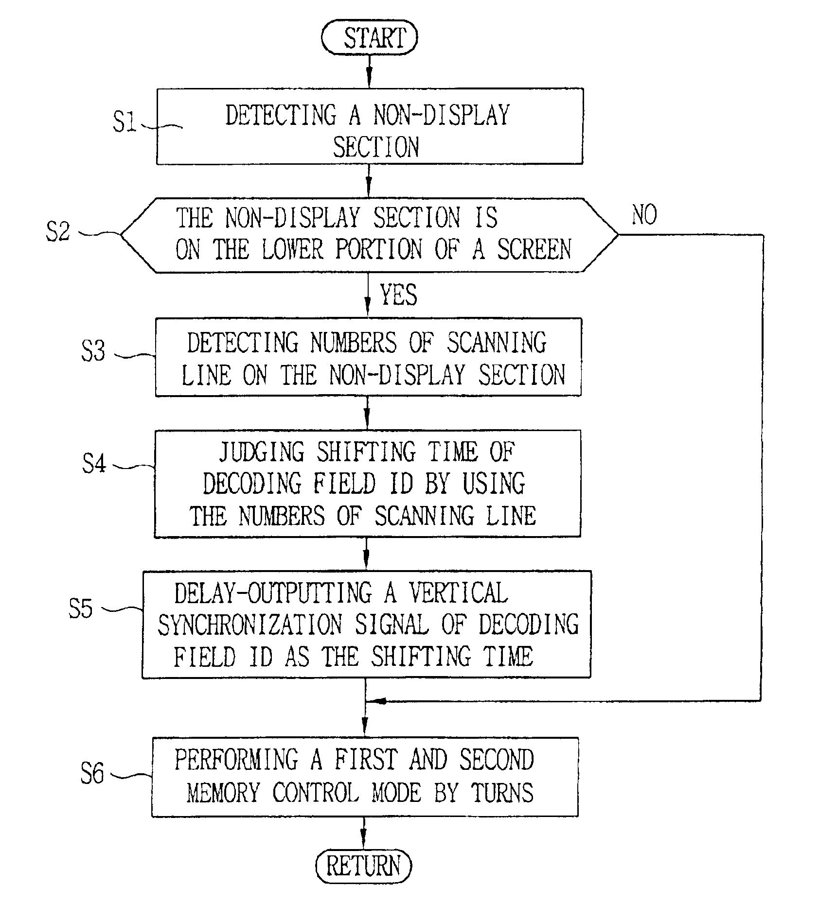
[0025]The other object of the present invention is to provide a method for decoding and storing the digital broadcasting signals which allows the decoder to exploit entire decoding time even with a B-gap where videos are not displayed on the lower portion of the screen.

Problems solved by technology

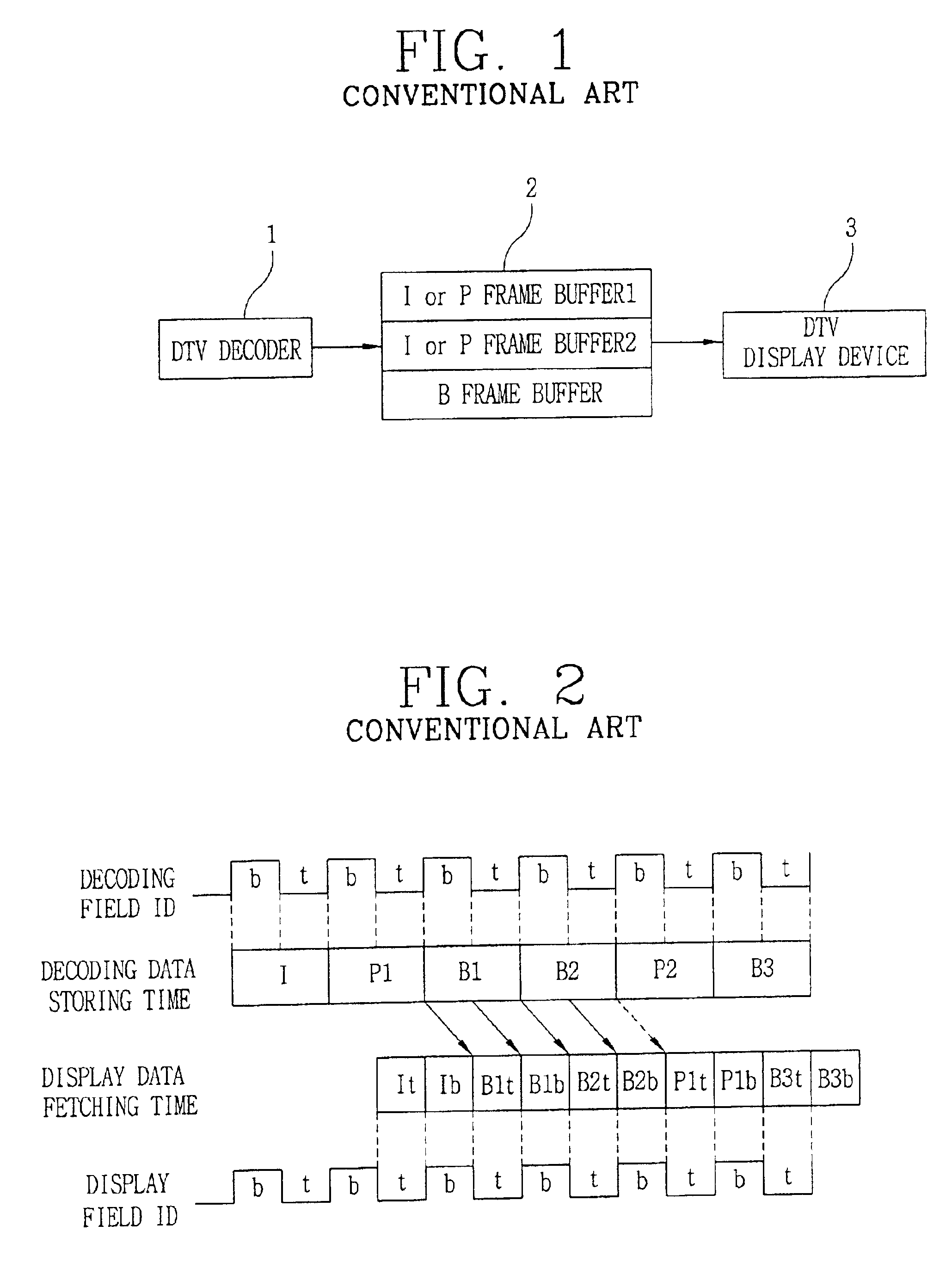
However, since the DTV set is quite expensive for general customers, there are much attentions on the development of a low price set-top boxes.
However, it is not easy to transfer the HD video signal to the graphic controller because such a high bandwidth video signal interface such as VIP2.0 is not popular yet and it causes heavy load for a local bus.
Therefore, is hard to overlay the HD program within the graphic controller.
The apparatus might have more than three frame buffers, but it causes the increase of the material cost.
But, it causes increase of the manufacturing cost.

Method used


Image

  • Method for decoding and displaying digital broadcasting signals
  • Method for decoding and displaying digital broadcasting signals
  • Method for decoding and displaying digital broadcasting signals

Examples


Embodiment Construction

[0038]Hereinafter, the preferred embodiments of the present invention will now be described in more detail.

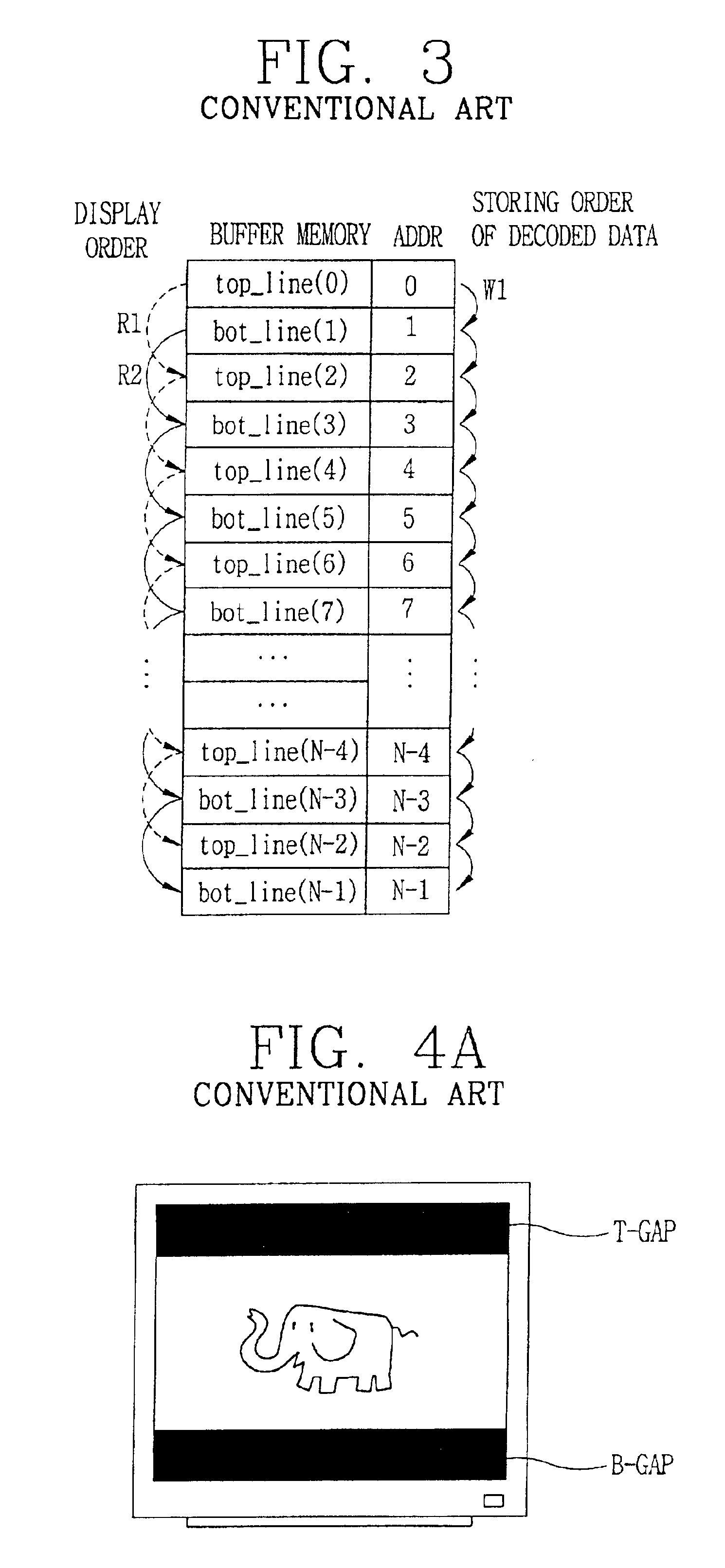
[0039]First, FIG. 6A is a memory map illustrating a first memory control mode of the present invention. The first half data of the first B frame (B1) is stored by skipping over one address (0, 2, 4, . . . , N−2) from the first address (0) in the order of W2.And the second half data of B1 is stored in the skipped addresses (1, 3, 5, . . . , N−1) in the order of W3.

[0040]In other words, the data is stored advance on the even addresses (2X, herein X=0, 1, 2, . . . ) W2, after that, the data is stored on the odd addresses (2X+1, herein X=0, 1, 2, . . . ) W3.

[0041]When the decoded data is stored by the first memory control mode, the top-field data (top_line(0)) is stored on the first address (0), the bottom_field data (bot_line(1)) is stored on the next address (2), and the top-field data (top_line(2)) is stored on the next address (4). Thus, two consecutive field lines, i.e., (top_...


PUM


Abstract

The present invention relates to a method for decoding and storing digital broadcasting signals which is capable of freely adjusting size and position of a broadcasting video window by preventing a frame buffer conflict between storing and fetching timing of the decoded data which can be occurred depending on the position and the size of the video window displayed on a screen, without expanding memory or upgrading speed of the decoder.

Description

BACKGROUND OF THE INVENTION[0001]1. Field of the Invention[0002]The present invention relates to a method for decoding and displaying digital broadcasting signals, in particular to a method for storing the decoded picture for preventing a frame buffer conflict irrespective of location and size of a display window on the screen in decoding and displaying digital broadcasting signals.[0003]2. Description of the Related Art[0004]The digital television (DTV) broadcasting has started in the United States since 1998. Many efforts have been made to develop DTV sets and set-top boxes for receiving the digital television signal. Recently, an interactive set-top box has been presented, which provides communication services based on the web by displaying a small window on the television screen while a user watches a television program.[0005]However, since the DTV set is quite expensive for general customers, there are much attentions on the development of a low price set-top boxes. PC (persona...

Claims


Application Information

Patent Timeline
IPC IPC(8): G06T1/60H04N5/46G09G5/00G09G5/38H04N7/01
CPCG06T1/60
Inventor KIM, SEE-HYUNLEE, HEE-SUB
Owner LG ELECTRONICS INC
Learn More