
Cooling set point control

a technology of cooling set point and control device, which is applied in the direction of domestic cooling apparatus, heating types, instruments, etc., can solve the problems of air stream that cannot reach 100% relative humidity, air having humidity which is still too high, and air in the enclosure may have excessive humidity, so as to reduce the cooling set point, improve comfort in the inside space, and reduce the energy consumption of the climate control system

Inactive Publication Date: 2005-05-17
ADEMCO INC
View PDF7 Cites 48 Cited by
  • Summary
  • Abstract
  • Description
  • Claims
  • Application Information

AI Technical Summary

Benefits of technology

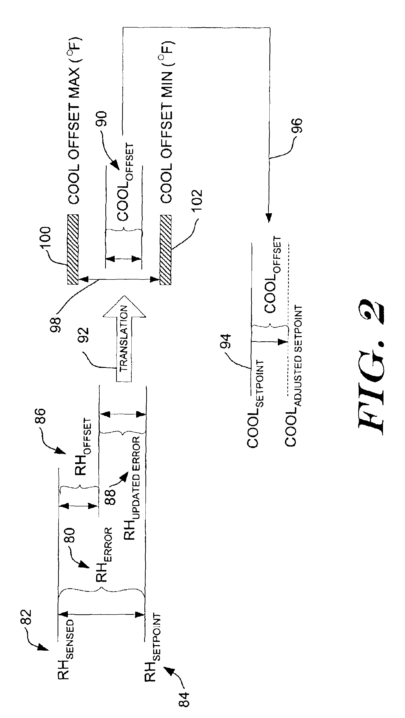
[0005]The present invention provides methods and apparatus for controlling the cooling set point value of a climate control system for an inside space. In one illustrative embodiment, a humidity error is determined as a function of the actual humidity in the inside space and a humidity set point value. The cooling set point value is then adjusted by a cooling offset that is a function of the humidity error. Under humid conditions, and when insufficient dehumidification occurs during a normal cooling cycle, lowering the cooling set point may provide further dehumidification, which may improve comfort in the inside space. Under less humid conditions, and when the humidity level in the inside space is already below the humidity set point value, increasing the cooling set point value may lower the energy usage of the climate control system while still providing comfort.
[0008]Under humid conditions, and when insufficient dehumidification occurs during a normal cooling cycle, the cooling set point may be decreased (i.e. decreased to a lower set point temperature) by the cooling offset value to provide further dehumidification to the air in the inside space. Under less humid conditions, and when the humidity level in the inside space is already below the humidity set point value, the cooling set point may be increased (i.e. increased to a higher set point temperature) by the cooling offset value to lower energy usage of the climate control system.

Problems solved by technology

All of the air in the air stream that passes through the air conditioner, however, may not reach 100% relative humidity because not all of the air is cooled to its dew point.
However, there are situations that can result in air having humidity which is still too high when the temperature requirement has been met.
But in cases of unusually high humidity or where the air conditioner capacity relative to the current environmental conditions does not result in sufficient dehumidification when the set point temperature is reached, it is possible for the air in the enclosure to have excessive humidity.

Method used


Image

  • Cooling set point control
  • Cooling set point control
  • Cooling set point control

Examples


Embodiment Construction

[0016]The following detailed description should be read with reference to the drawings, in which like elements in different drawings are numbered in like fashion. The drawings, which are not necessarily to scale, depict selected embodiments and are not intended to limit the scope of the invention. Those skilled in the art will recognize that many of the examples provided may have suitable alternatives that could be utilized without departing from the spirit of the present invention.

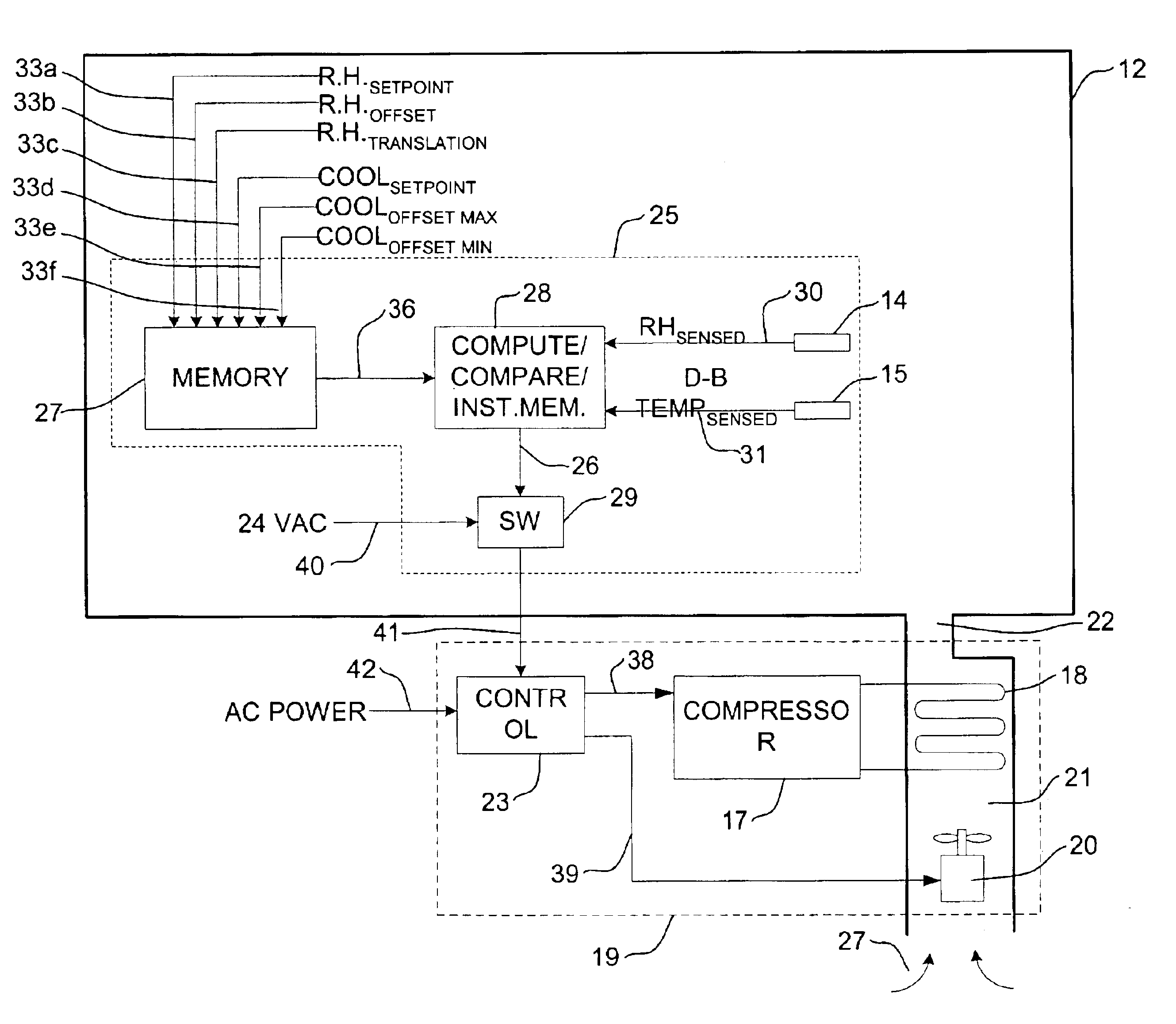
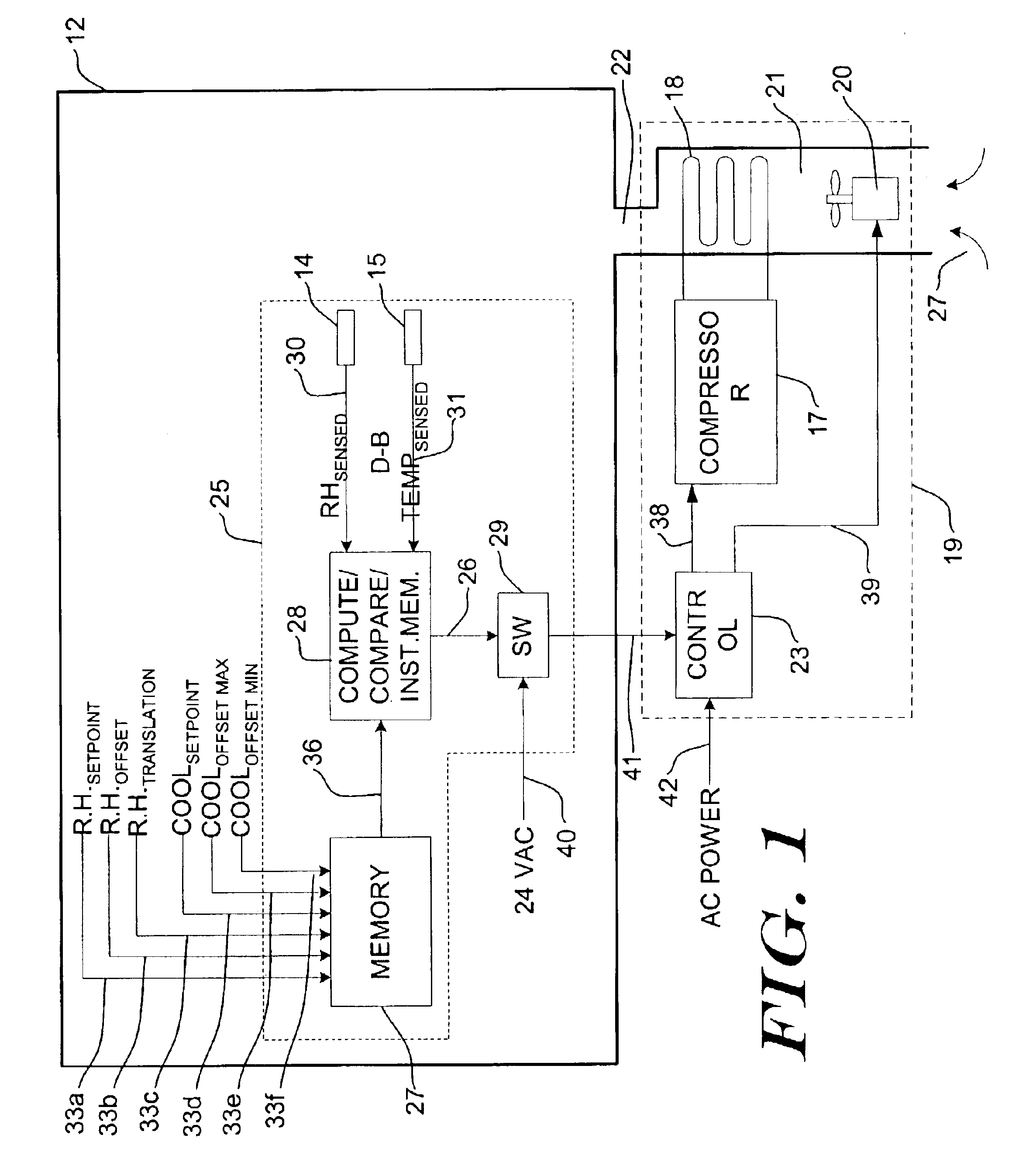
[0017]FIG. 1 is a block diagram of an air conditioning installation using an illustrative embodiment of the present invention. In FIG. 1, a climate control system is shown for controlling the air temperature of an inside space 12. In the illustrative embodiment, the inside space 12 receives cooled and dehumidified air from a conventional air conditioning unit 19 which operates on externally supplied AC power provided on conductors 42. A control element 23 switches power to a compressor 17 and a blower 20 ...


PUM


Abstract

Methods and apparatus for controlling the cooling set point value of a climate control system are provided. In one illustrative embodiment, a humidity error is determined as a function of the actual humidity in the inside space and a humidity set point value. The cooling set point value is then adjusted by a cooling offset that is a function of the humidity error. Under humid conditions, and when insufficient dehumidification occurs during a normal cooling cycle, lowering the cooling set point may provide further dehumidification, which may improve comfort in the inside space. Under less humid conditions, and when the humidity level in the inside space is already below the humidity set point value, increasing the cooling set point value may lower the energy usage of the climate control system while still providing comfort.

Description

BACKGROUND[0001]This invention is directed generally to control of indoor climate modifying apparatus such as an air conditioning unit or a furnace for maintaining comfort for the occupants of enclosures. The more important application is in controlling operation of air conditioners, and the discussion and disclosure following will be based primarily on the air conditioning case. The invention will typically be implemented in an electronic thermostat which uses a microcontroller in conjunction with a temperature sensor and a humidity sensor for controlling opening and closing of a solid state switch which controls the flow of operating current to the air conditioning control module.[0002]Thermostats typically in use now which direct operation of air conditioners use dry-bulb temperature as the controlled variable. The term “dry-bulb temperature”, as used herein, means the actual temperature of the air as measured by a typical thermometer. The terms “temperature” and “air temperature...

Claims


Application Information

Patent Timeline
Patent Type & Authority Patents(United States)
IPC IPC(8): F24F11/00G05D22/02G05D22/00
CPCF24F11/0008G05D22/02F24F11/0015F24F11/30F24F2110/20F24F11/64
Inventor STRAND, ROLF L.
Owner ADEMCO INC
Learn More