Ladder bag and method of use

Inactive Publication Date: 2005-05-17
ZUPAN KIM ALLYSON
View PDF7 Cites 18 Cited by
  • Summary
  • Abstract
  • Description
  • Claims
  • Application Information

AI Technical Summary

Benefits of technology

[0007]The primary object of this invention is to provide a rugged means for conveniently transporting tools and equipment to an elevated work site, promptly placing them in a securely fixed and easily accessible position while work at the elevated site progresses, and then when no longer needed at that site allowing for quick release and relocation. A further object of this invention is to provide a rugged device for the safe transport and storage of equipment and tools to an elevated work site that is versatile and capable of connection to the top surface of a step ladder as well a ladder rung, scaffold, the railing used on a lift, and other structures able to support a person needing to reach high work sites. It is also an object of this invention to provide a rugged device that is capable of safely transporting and storing power tools to an elevated work site. A further o

Problems solved by technology

Having to do this is time consuming an inefficient.
Also, repeated climbing up and down ladders and scaffold tires a worker and over time can adversely affect some workers' leg muscles and knees.
Most bags and trays currently used to support tools and equipment at elevation are too small to prevent frequent dismounts, not easily or rapidly secured and released at elevation, not adapted for secure transport and storage of power

Method used


Image

  • Ladder bag and method of use
  • Ladder bag and method of use
  • Ladder bag and method of use

Examples


Embodiment Construction

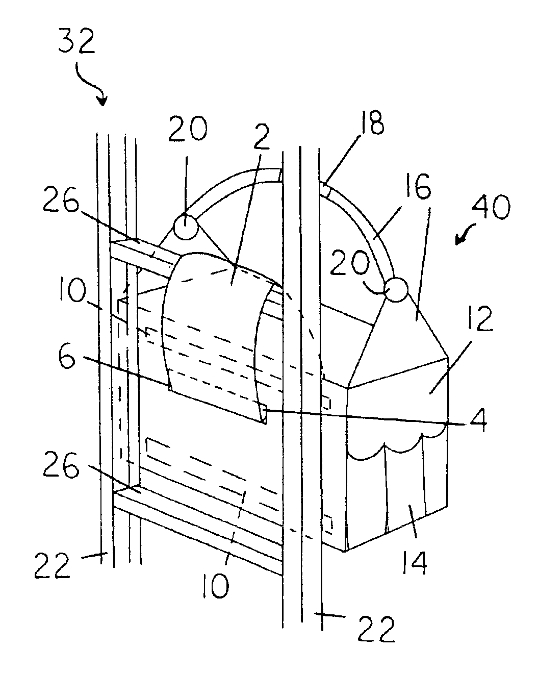
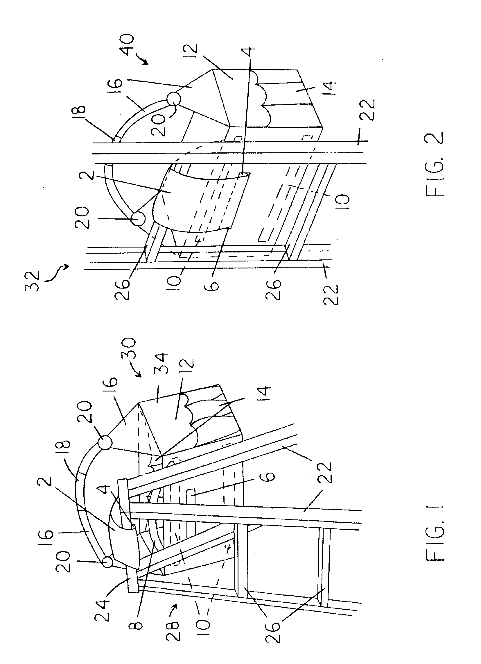
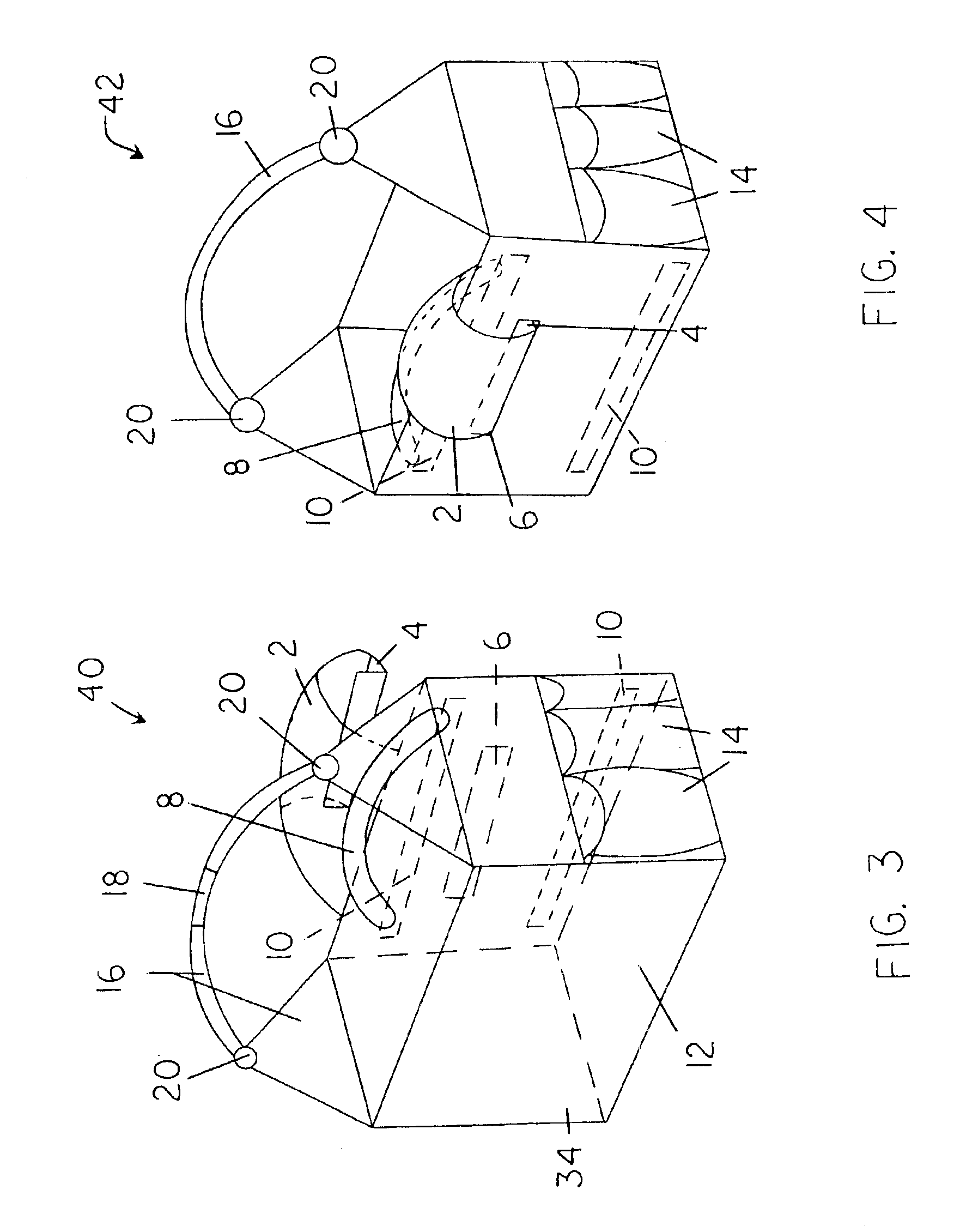
[0018]FIGS. 1-5 show several closely related preferred embodiments 30, 40, and 42 of the present invention ladder bag capable of transporting a variety of handheld tools and other equipment (not shown) to an elevated work site and fixing them securely in a location of convenient access to a user (not shown). Multiple support configurations are illustrated for the present invention. For example, in FIG. 1, the present invention's generally U-shaped clip 4, located on the distal end of support band 2, is connected to a downwardly depending lip or edge on the user side of a step ladder's or A-frame ladder's top surface 28. Support band 2 is extended across ladder top 28, but not yet taut. When the force of gravity on bag 34 and any contents (not shown) pull support band 2 taut, clip 4 cannot thereafter be easily inadvertently disengaged from its ladder connection and the attached bag 34 becomes securely suspended in an out-of-the-way yet easily accessible position against the far surfa...


PUM


Abstract

A rugged braced bag for securing hand tools and other equipment to a ladder, scaffold, or mechanical lift within easy reach of a worker. The bag has wide flexible support band with a rigid distal clip configured for engagement with a slot in one of its upstanding walls. Alternatively, the bag can be secured by the support band and clip engaging a ladder top, or the band encircling a ladder rung or horizontally-extending bar with the clip inserted into the slot. The bag has a shoulder strap and release handle used for raising the bag and ready release of the clip from its engaged position. Optionally, the bag can have compartments, pockets, and/or a removable liner. Applications can include, but are not limited to, use by carpenters, painters, electricians, plumbers, homeowners, and anyone needing to use tools and equipment while on a ladder, scaffold, lift, or other raised support structure.

Description

CROSS-REFERENCES TO RELATED APPLICATIONS[0001]None.BACKGROUND OF THE INVENTION[0002]1. Field of the Invention[0003]This invention relates to the field of bags and trays used to transport handheld tools and other equipment to an elevated work site, and thereafter safely support them from the top surface of an A-frame ladder, a ladder rung, scaffold, and the like, in a convenient location for easy user access. The present invention is quickly attached to and released from a support structure via use of a clip on the distal end of a support band being inserted into a horizontally-extending slot in one of its own vertical walls or alternatively with its clip engaging the downwardly extending lip or edge of a horizontally-extending surface, such as an A-frame ladder top. The weight of the bag and its contents tightens the flexible support band to which the clip is attached, so that the clip cannot become disengaged until it is deliberately released. When clip release is desired, an upwar...

Claims


Application Information

Patent Timeline
IPC IPC(8): B25H3/00B25H3/02E06C7/14
CPCE06C7/14B25H3/02E04G5/003
Inventor ZUPAN, KIM ALLYSON
Owner ZUPAN KIM ALLYSON
Why Eureka
Try Eureka