Flashlight

Active Publication Date: 2005-05-17
W T STOREY
View PDF44 Cites 128 Cited by
  • Summary
  • Abstract
  • Description
  • Claims
  • Application Information

AI Technical Summary

Benefits of technology

[0014]The present invention provides a flashlight which, in its preferred form, is intended to run continuously over a 10 hour period or more on one set of “D” cells or over 20 hours on 2 sets. It will be obvious that any size of cells can be utilized and it currently contemplated that a smaller version of the flashlight which utilizes 2 sets of “AA” cells would be of particular utility although, with smaller cells, the number of hours of continuous illumination without replacement of cells would be significantly fewer. A second microprocessor controlled circuit allows the flashlight to switch from one set of cells to the other, which provides uninterrupted use. An indicator is provided to show which set of cells is in use and, preferably, to also show the degree to which such cells have been drained. A new set of cells can replace the drained set while the flashlight is in use. A microprocessor circuit also allows the light to remain bright white throughout the lif

Problems solved by technology

The use of such a high resistance element, while initial costs a

Method used


Image

  • Flashlight
  • Flashlight
  • Flashlight

Examples


Embodiment Construction

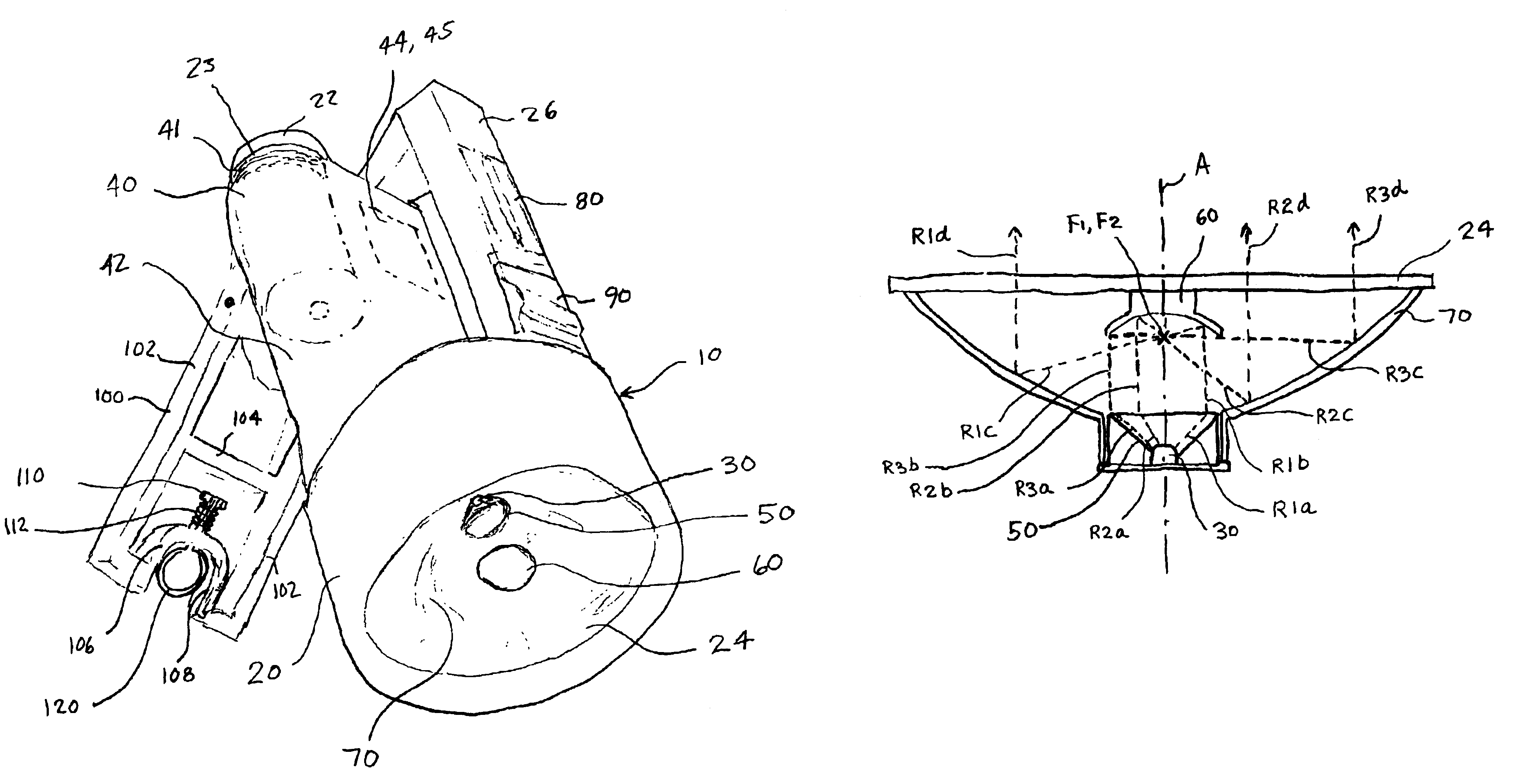
[0041]Referring to the figures, the flashlight 10 has a housing 20. The housing 20 has a cell compartment 42 which can be accessed by a pair of end caps 22. A rubber o-ring 23 is preferably provided on each end cap 22 to provide a water resistant means to enclose the cells 40 within the housing 20. A pair of cylindrical (rather than typical conical) shaped coil springs 41 are utilized to firmly hold the cells 40 in electrical contact with the necessary components to illuminate LED 30 or strobe 80 when desired. The housing 20 also includes a transparent lens 24 on the front end of the housing and a carrying handle 26 is provided.

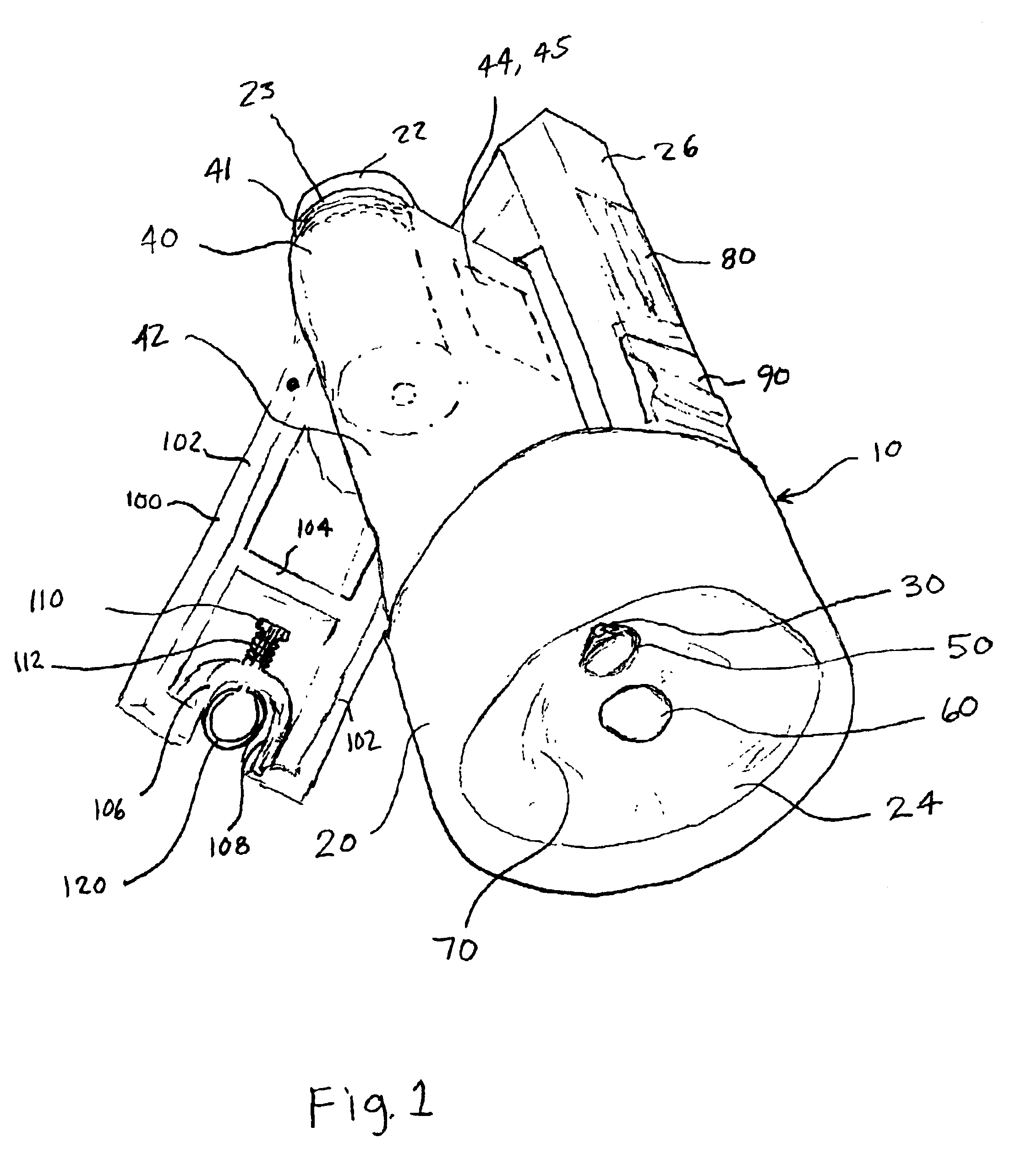
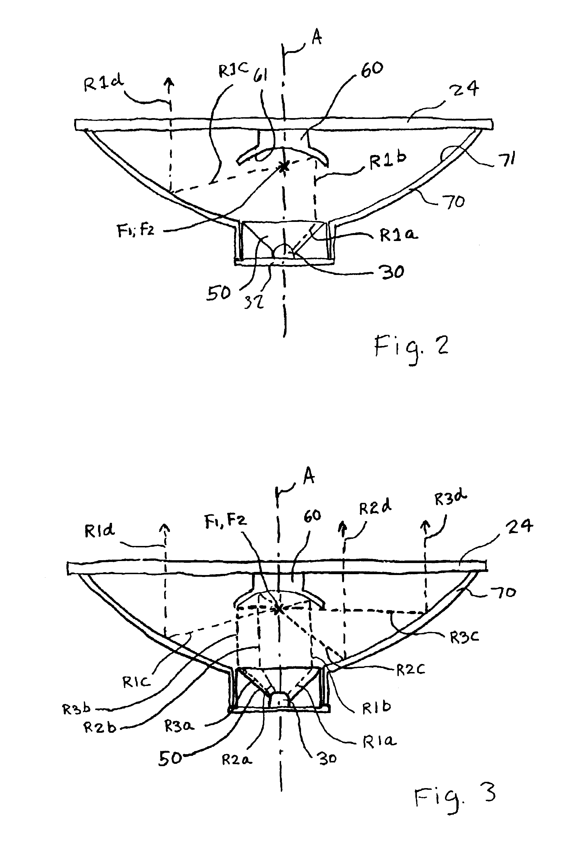
[0042]A one watt bright white light LED light source 30 is provided. Collimating optics 50 are attached adjacent said LED light source 30. A first paraboloid reflector 60 is provided on an inner surface of transparent lens 24. Depending upon the desired location for the focus point F1 of the first paraboloid reflector 60, however, it may be necessary to mount...


PUM


Abstract

A flashlight is disclosed which includes a housing adapted to receive one or more battery cells and having a transparent lens on a forward end thereof. An LED light source connected to the cell is utilized in conjunction with collimating optics positioned adjacent the LED to refract rays of light from the LED forwardly. A first paraboloid reflector having a concave reflective surface is positioned within said housing to receive rays of light from the collimating optics and to reflect the rays rearwardly and a second paraboloid reflector having a concave reflective surface is positioned within said housing to receive rays of light reflected rearwardly from the first paraboloid reflector and to further reflect the rays forwardly through the transparent lens.

Description

BACKGROUND OF THE INVENTION[0001]1. Field of the Invention[0002]The present invention relates to a flashlight. More specifically, it relates to an extremely durable and long lasting flashlight utilizing a light emitting diode (hereinafter “LED”) light source in combination with a pair of paraboloid reflectors making the flashlight particularly useful for police, fire, rescue and emergency services workers and military personnel.[0003]2. Description of the Prior Art[0004]A variety of prior art flashlights have been proposed.[0005]Matthews, U.S. Pat. No. 6,386,730, discloses a flashlight having a head with two merged yet independent lamp / reflector systems. While Matthews teaches the provision of two reflectors, both reflectors are simply used to independently focus light from two light sources into the forwardly directed beam configurations.[0006]McDermott, U.S. Pat. No. 5,894,196, discloses a compact lighting device including a light concentrating reflector directing light emitted by...

Claims


Application Information

Patent Timeline
IPC IPC(8): F21V7/00F21L4/00F21L4/02F21V13/00F21V13/04F21V21/06F21V21/40F21V5/04F21V23/04F21V5/00F21V31/00
CPCF21L4/027F21V7/0033F21V21/06F21V21/406F21V13/04F21V5/04F21V7/0008F21Y2101/02F21V23/0414F21V31/00F21Y2115/10
Inventor STOREY, WILLIAM T.PROBST, BRIAN E.GORRIE, JOSEPH E.
Owner W T STOREY
Why Eureka
Try Eureka