Label printer for optical disk such as CD

a technology of optical disk and label printer, which is applied in the field of label printers, can solve the problems of troublesome mounting of another troublesome operation of mounting a cd on the adapter, and high cost, so as to avoid an increase of the number of parts and the structural complexity, simplify the interlocking mechanism, and prevent an increase of the size of the label printer

Inactive Publication Date: 2005-05-17
ORIENT INSTR COMP CO LTD
View PDF9 Cites 15 Cited by
  • Summary
  • Abstract
  • Description
  • Claims
  • Application Information

AI Technical Summary

Benefits of technology

[0019]Furthermore, it is preferable that the disk holding means serves both as a disk holding means for holding the name card type disk in the name card type disk loading recessed portion and a disk holding means for holding a 12 cm-diameter complete round disk in the 12 cm-diameter complete round disk loading recessed portion. In this case, it is possible to avoid an increase of the number of parts and the structural complexity due to separate pieces and simplify the interlocking mechanism with the disk transferring tray.
[0020]It is preferable that the name card type disk loading recessed portion is formed at a rear portion of the complete round disk loading recessed portion and that a bottom surface of the recessed portion is positioned lower than a bottom surface of the complete round disk loading recessed portion. In this case, the disk transferring tray can be approximately the same size as a disk transferring tray of a conventional label printer, preventing an increase of the size of the disk transferring tray, which in turn can prevent an increase of the size of the label printer.
[0021]It is preferable that the name card type disk loading recessed portion is formed into an approximately rectangular shape as seen from the above corresponding to a plan shape of a name card type optical disk and that the rear end edge is positioned in the vicinity of a rear most portion of a virtual complete circle of the complete round disk loading recessed portion. In this case, the holding position of the disk holding means against the complete round disk and that against the name card type disk can be set to be the same or almost the same, which makes the holding force of the disk holding means against the name card type disk and the complete round disk almost constant. This prevents excessive or insufficient holding of either disk. Furthermore, since the movable region of the ink head in the printer body can be the same as a conventional label printer or slightly larger, the basic structure of a conventional label printer can be used as it is.
[0022]Furthermore, it is preferable that the name card type disk loading recessed portion is formed such that a long side thereof crosses in a transferring direction of the disk transferring tray. In this case, a name card type disk can be held in the widthwise direction, which reduces the warping of a name card type disk due to the holding as compared with the case in which the disk is held in the longitudinal direction. Furthermore, since the degree of occupation of the name card type disk loading recessed portion to the complete round disk loading recessed portion can be minimized, the printing on a 12 cm-diameter disk by a printer head can be stabilized.
[0023]It is preferable that a disk ejecting finger insertion aperture communicating with the name card type disk loading recessed portion is formed in the complete round disk loading recessed portion. In this case, in cases where a name card type disk is loaded on the disk transferring tray or unloaded therefrom, the name card type disk can be easily unloaded. Although the position of the aperture is not limited to a specific position, it is preferable to set the position at a position corresponding to the central aperture of the disk because printing by the ink head is not performed at the position.

Problems solved by technology

These manufacturing processes are reasonable from the aspect of cost performance in cases where a large number of CD-ROMs are manufactured at once, but may come in extremely high cost in cases where several tens of or two or three hundreds of CD-ROMs are manufactured.
Although each operation is generally simple, in a case where there are tens or hundreds of CDs, the operations of mounting a CD on the adapter, removing the CD from the adapter after the completion of the label printing and then mounting another new CD on the adapter are troublesome.
More importantly, such an adapter cannot be used in the aforementioned automatic machine that automatically performs from copies of CDs to label printing of CDs.

Method used


Image

  • Label printer for optical disk such as CD
  • Label printer for optical disk such as CD
  • Label printer for optical disk such as CD

Examples


Embodiment Construction

[0035]Hereinafter, a best mode for carrying out the invention will be explained with reference to drawings.

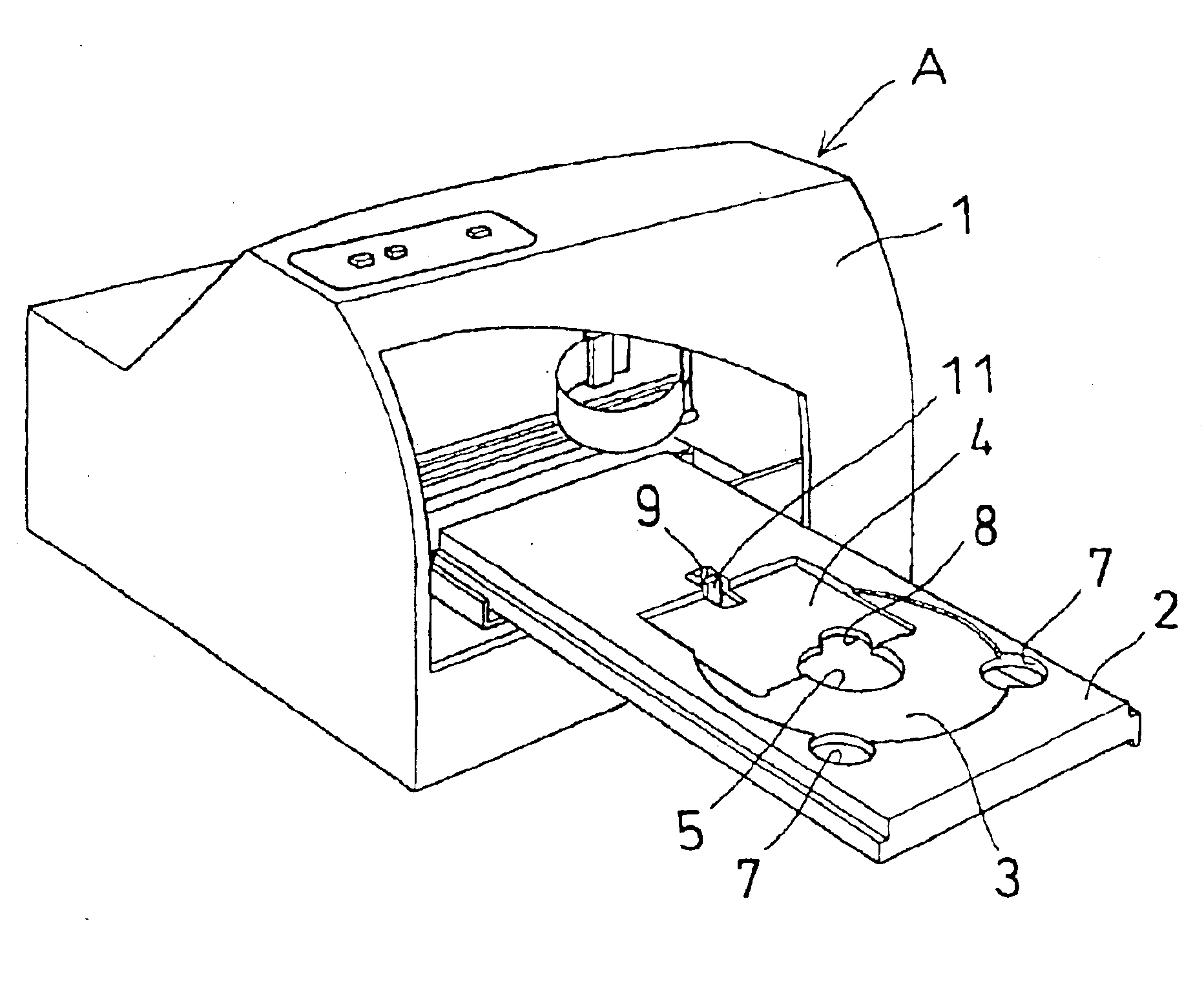
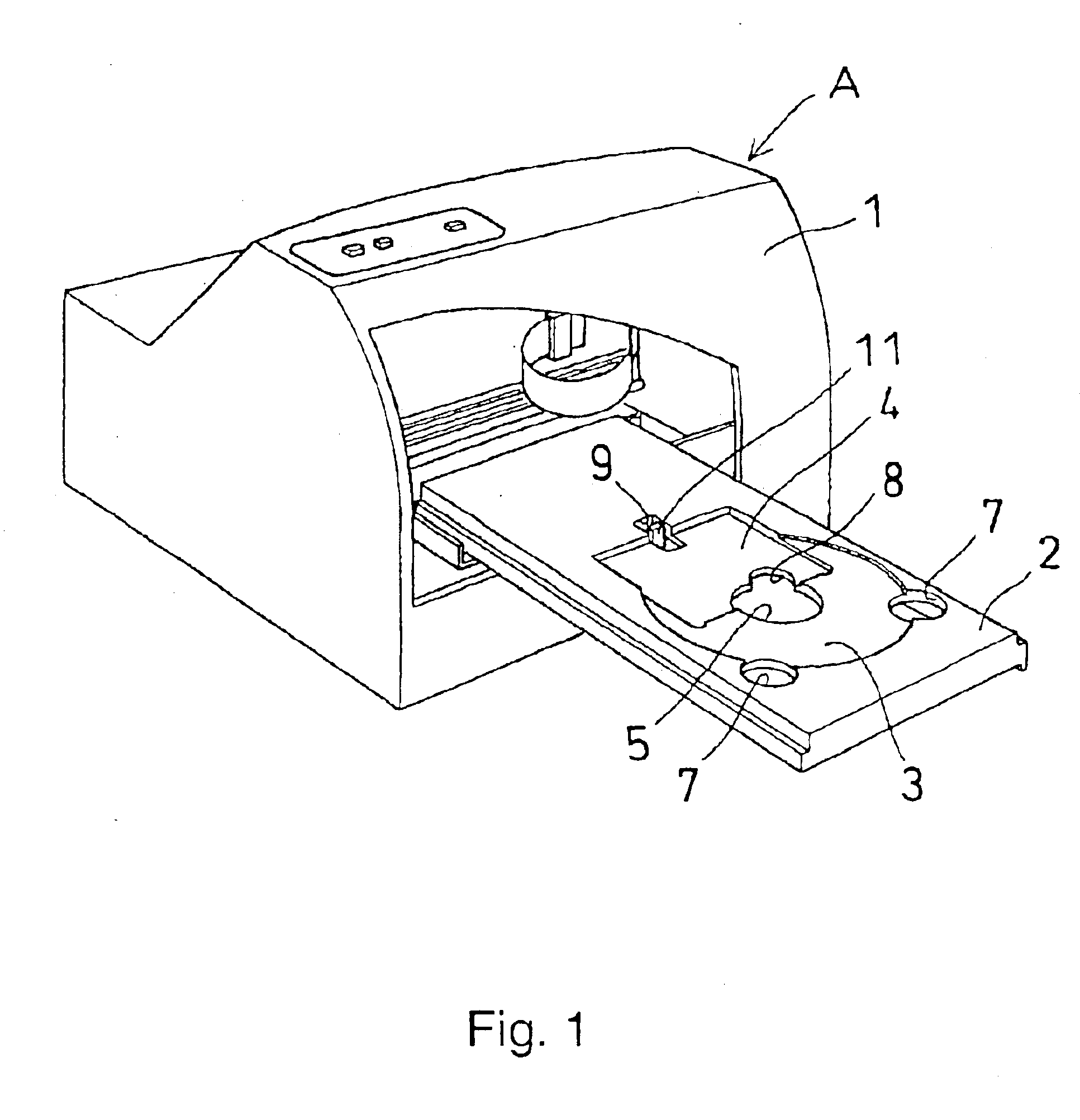
[0036]FIG. 1 is a perspective view showing the state in which a disk transferring tray 2 is ejected from a printer body 1 of a label printer A according to the present invention. The disk transferring tray 2 is in an empty state in which no disk is loaded in either recessed portions 3 and 4, the 12 cm-diameter complete around disk loading recessed portion 3 or the name card type disk loading recessed portion 4.

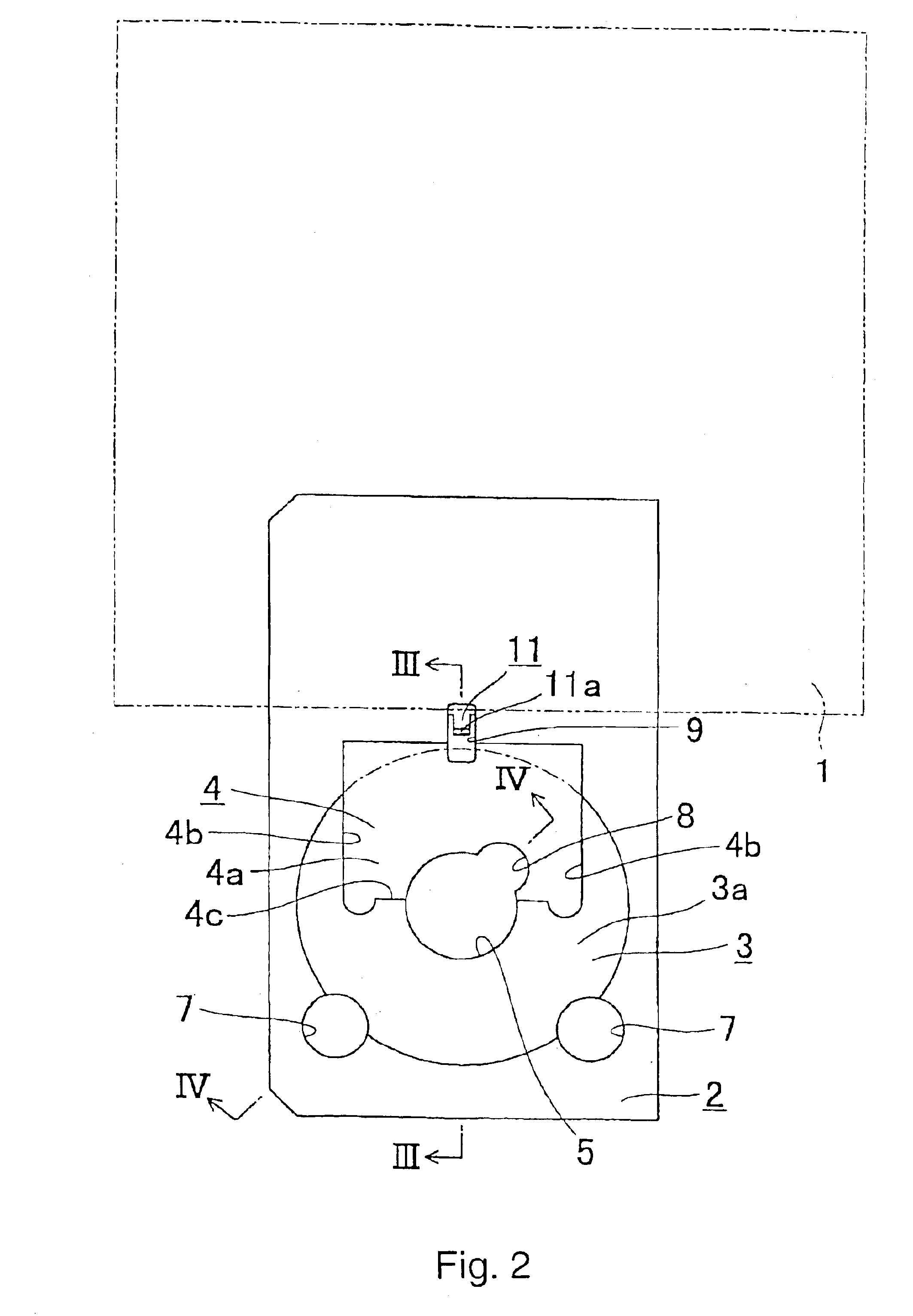
[0037]As shown in FIG. 2, the 12 cm-diameter complete round disk loading recessed portion 3 has an inner periphery that coincides with a virtual complete circle having a diameter larger than the diameter of 12 cm by 1 mm and a bottom surface 3a located lower than the upper surface of the tray by about 1 mm. At the rear portion of the recessed portion 3, a name card type disk loading recessed portion 4 having a bottom surface 4a located lower than the bottom surface 3a of ...


PUM

PropertyMeasurementUnit
diameteraaaaaaaaaa
diameteraaaaaaaaaa
diameteraaaaaaaaaa

Abstract

A label printer suitable for label printing of a name card type optical disk as well as a 12 cm-standard complete round disk, wherein a 12 cm-diameter complete round disk loading recessed portion 3 is provided in a disk transferring tray 2 allowed to be inserted and ejected from a printer body 1, and a name card type disk loading recessed portion 4 having a bottom surface positioned lower than the bottom surface of the complete round disk loading recessed portion 3 is provided at the rear portion of the complete round disk loading recessed portion 3. At a rear portion of the name card type disk loading recessed portion 4, an aperture for allowing the movement of the tip protruded portion 11a of a disk holding means 11 in the fore-and-aft direction of the printer body 1 is provided. When the disk transferring tray 2 is ejected from the printer body 1, a 12 cm-diameter complete disk D1 or a name card disk D2 is loaded in the corresponding disk loading recessed portion 3, 4 and then the disk transferring tray 2 is inserted in the printer body 1, the 12 cm-diameter complete disk D1 or the name card type disk D2 is pressed against the inner periphery of the corresponding disk loading recessed portion 3, 4 to be immovably held. Therefore, an excellent label printing with no blur can be performed.

Description

TECHNICAL FIELD[0001]The present invention relates to a label printer for performing label printing of an optical disk such as the so-called CD, DVD, etc., and more particularly to a label printer preferably used for label printing of a name card type optical disk as well as a standard 12 cm-diameter complete round disk.BACKGROUND ART[0002]Recently, the so-called compact disks (hereinafter referred to as “CD(s),” which will be referred to as a generic term of various CDs including not only the so-called music CD but also CD-ROM, CD-R, CD-RW, etc.) among optical disks that have become essential as information recording mediums have been widely used.[0003]For example, a CD-ROM exclusively used for reading recorded information is manufactured via a creation of the so-called metal master, a creation of a metal mother as a backup of the metal master, a creation of a stamper, a stamping with the stamper, a creation of a reflection layer, a formation of a protective layer on the reflection...

Claims


Application Information

Patent Timeline
Patent Type & Authority Patents(United States)
IPC IPC(8): B41J3/407
CPCB41J3/4071
Inventor OBARA, DAISUKE
Owner ORIENT INSTR COMP CO LTD
Why Eureka
Try Eureka