Guide connector

Inactive Publication Date: 2005-05-17
DELTA ELECTRONICS INC
View PDF5 Cites 19 Cited by
  • Summary
  • Abstract
  • Description
  • Claims
  • Application Information

AI Technical Summary

Benefits of technology

[0008]Therefore, the object of the present invention is to provide a guide connector, to connect two circuit boards reliably and conveniently.
[0009]To achieve the foregoing object, the guide connector according to the invention aims to connect a first circuit board and a second circuit board for transmitting signals between the two, and the distance between the two circuit boards is shortened as desired, without affecting its functions.
[0012]The guide connector includes a first anchor dock, a second anchor dock, a first guiding dock and a second guiding dock. Metal transmission lines have two ends inserting respectively to the insert holes of the two circuit boards, to transmit signals there between. The first anchor dock and the second anchor dock are coupled with the metal transmission lines to fix the relative positions thereof. The first guiding dock is coupled on the metal transmission lines in a sliding manner between the first anchor dock and the free ends of the metal transmission lines. It has two ends, holding respectively a guiding post, which corresponds to each of the two guiding bores of the first circuit board, to facilitate alignment of the metal transmission lines with the insert holes on the first circuit board. The first guiding dock slides freely to make adjustment according to the distance between the first and the second circuit boards. The second guiding dock is coupled with the metal transmission lines in a sliding manner and located between the first and the second anchor docks, to couple latch members located on two ends into the latch bores, thereby, to facilitate steady insertion of the metal transmission lines into the insert holes of the second circuit board.

Problems solved by technology

First, the diameters of the metal transmission line 501 and insert holes 402 on the circuit boards 400 are very small. During assembly on production lines in large number, it tends to occur that the metal transmission lines 501 do not completely align with the insert holes 402 because of equipment deviations and tolerances. This results in damage of the metal transmission lines 501 or circuit boards 400 and causes drop of production yield.
Second, connection of the connector 500 and the circuit boards 400 solely relies on coupling of the metal transmission lines 501 and the insert holes 402. This is not a reliable structure. The connector 500 is easily damaged because of external shaking. As a result, signal transmission in the programmable logic controller will be affected.
Third, the conventional connector 500 is a fixed apparatus. If the distance between two circuit boards 400 is shrunk, the original connector 500 becomes useless, and a new one has to be fabricated. This results in additional costs and waste of resources.

Method used


Image

  • Guide connector
  • Guide connector
  • Guide connector

Examples


Embodiment Construction

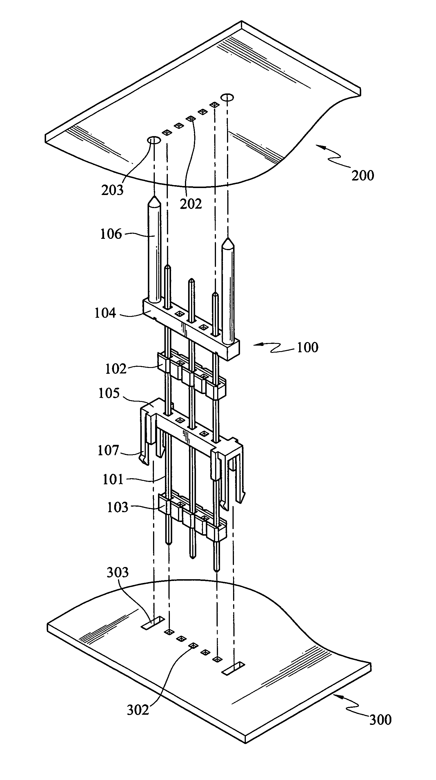
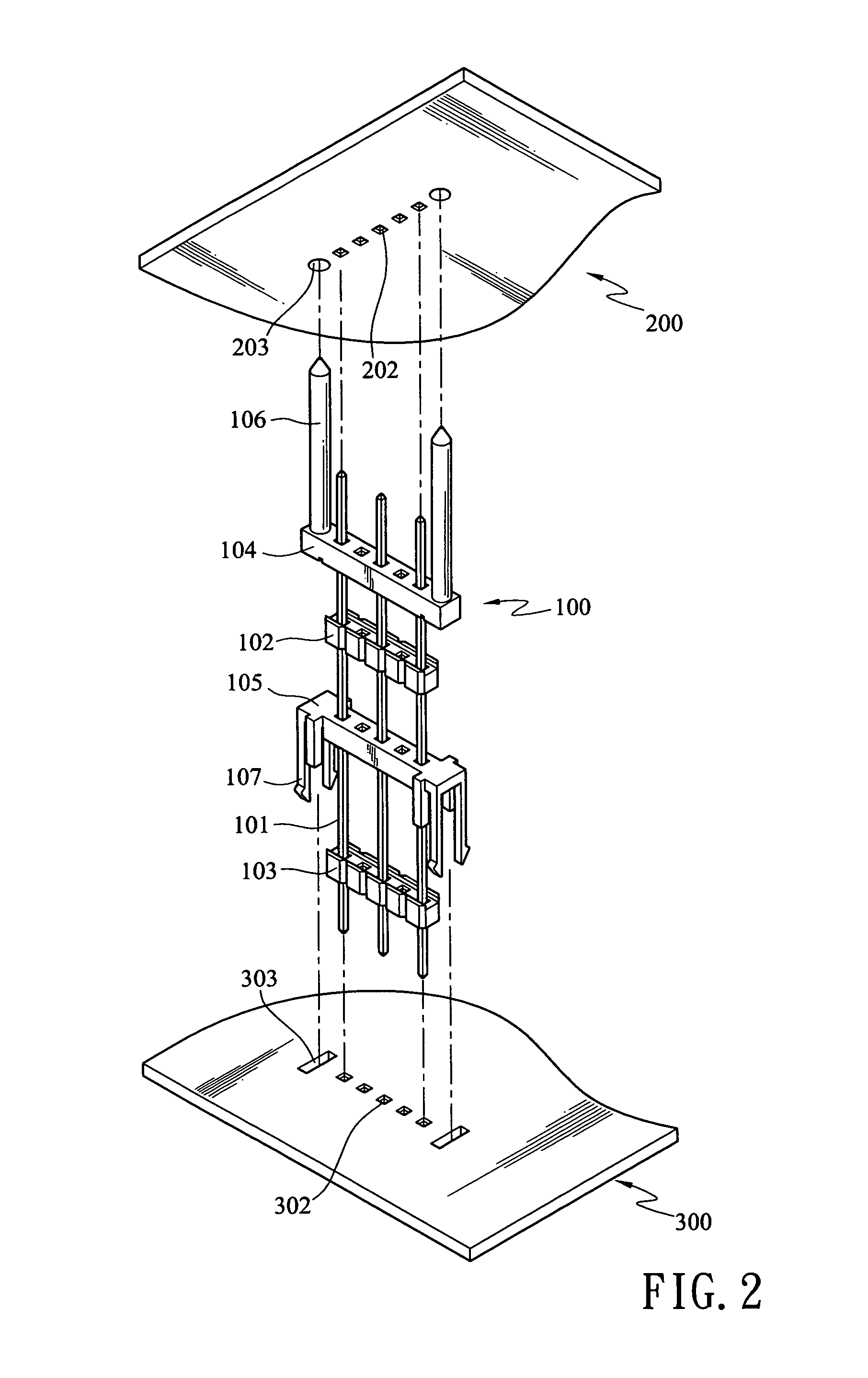
[0016]Refer to FIG. 2 for the guide connector and two circuit boards of the invention. The guide connector 100 is adopted for use on various types of electronic devices (such as programmable logic controllers) to connect two circuit boards 200 and 300 to transmit signals between the two.

[0017]The programmable logic controller in an embodiment of the invention includes a first circuit board 200 and a second circuit board 300 that have respectively circuits located thereon to execute related commands. The first and second circuit boards 200 and 300 have respectively a plurality of insert holes 202 and 302, to connect to the guide connector 100, to transmit signals.

[0018]The first circuit board 200 further has two guiding bores 203 located on two outer sides of the insert holes 202.

[0019]The second circuit board 300 further has two latch bores 303 located on two outer sides of the insert holes 302.

[0020]The guide connector 100 includes a plurality of metal transmission lines 101, a fir...


PUM


Abstract

A guide connector aims to connect two circuit boards to transmit signals between the two. The guide connector has a second guiding dock latching on one circuit board so that free ends of metal transmission lines of the guide connector may be securely inserted into insert holes of the circuit board. A first guiding dock is provided to connect other circuit board to enable other free ends of the metal transmission lines to be aligned with and inserted into insert holes of the other circuit board.

Description

FIELD OF THE INVENTION[0001]The present invention relates to a guide connector for connecting two circuit boards to transmit signals.BACKGROUND OF THE INVENTION[0002]Refer to FIG. 1 for a conventional guide connector that connects two circuit boards to meet multiple functional requirements of a programmable logic controller. The programmable logic controller usually has a plurality of circuit boards 400 to execute different operational requirements. A connector 500 is provided to connect two circuit boards 400 to transmit signals there between.[0003]The conventional connector 500 consists of metal transmission lines 501 and two anchor docks 502. The metal transmission lines 501 have two free ends, inserting respectively into insert holes 402, formed on the two circuit boards 400 for transmitting signals there between. The two anchor docks 502 couple and hold the metal transmission lines 501 to maintain the relative coupling positions.[0004]The structure set forth above has drawbacks...

Claims


Application Information

Patent Timeline
IPC IPC(8): H01R13/629
CPCH01R12/52H01R13/629
Inventor CHIANG, THOMAS
Owner DELTA ELECTRONICS INC
Why Eureka
Try Eureka