Rotary Mechanical Vibration Mechanism

Active Publication Date: 2010-09-23
RAYTHEON CO
View PDF22 Cites 7 Cited by
  • Summary
  • Abstract
  • Description
  • Claims
  • Application Information

AI Technical Summary

Benefits of technology

[0006]In accordance with another embodiment of the present invention, a system for extracting seized components may include a gripping mechanism that attaches to a seized component. The system may additionally include a camlock mechanism attached to the gripping mechanism by a shaft. The camlock mechanism may be capable of moving the gripping mechanism a predetermined distance, thereby fastening the gripping mechanism to the seized component. The system may also include a power transfer mechanism that may be capable of translating a received rotational force to a linear force. The linear force may pull a threaded axis attached to the gripping mechanism outward, thereby extracting the seized component. Additionally, the system may include a vibration mechanism that may be capable of generating vibration that facilitate the extraction of seized components.
[0007]Important technical advantages of certain aspects of the present invention include providing a reliable and convenient method of extracting mechanical and el

Problems solved by technology

In electro-mechanical systems that contain subcomponents, exposure to weather elements can cause various subcomponents to seize to their housings.
Particularly problematic are antenna arrays consisting of antenna elements.
Antenna arrays are typically exposed to the environment with relatively little protection.
This oxidation, combined with natural build-up of particulate matter makes successful damage-free extraction of the

Method used


Image

  • Rotary Mechanical Vibration Mechanism
  • Rotary Mechanical Vibration Mechanism
  • Rotary Mechanical Vibration Mechanism

Examples


Example

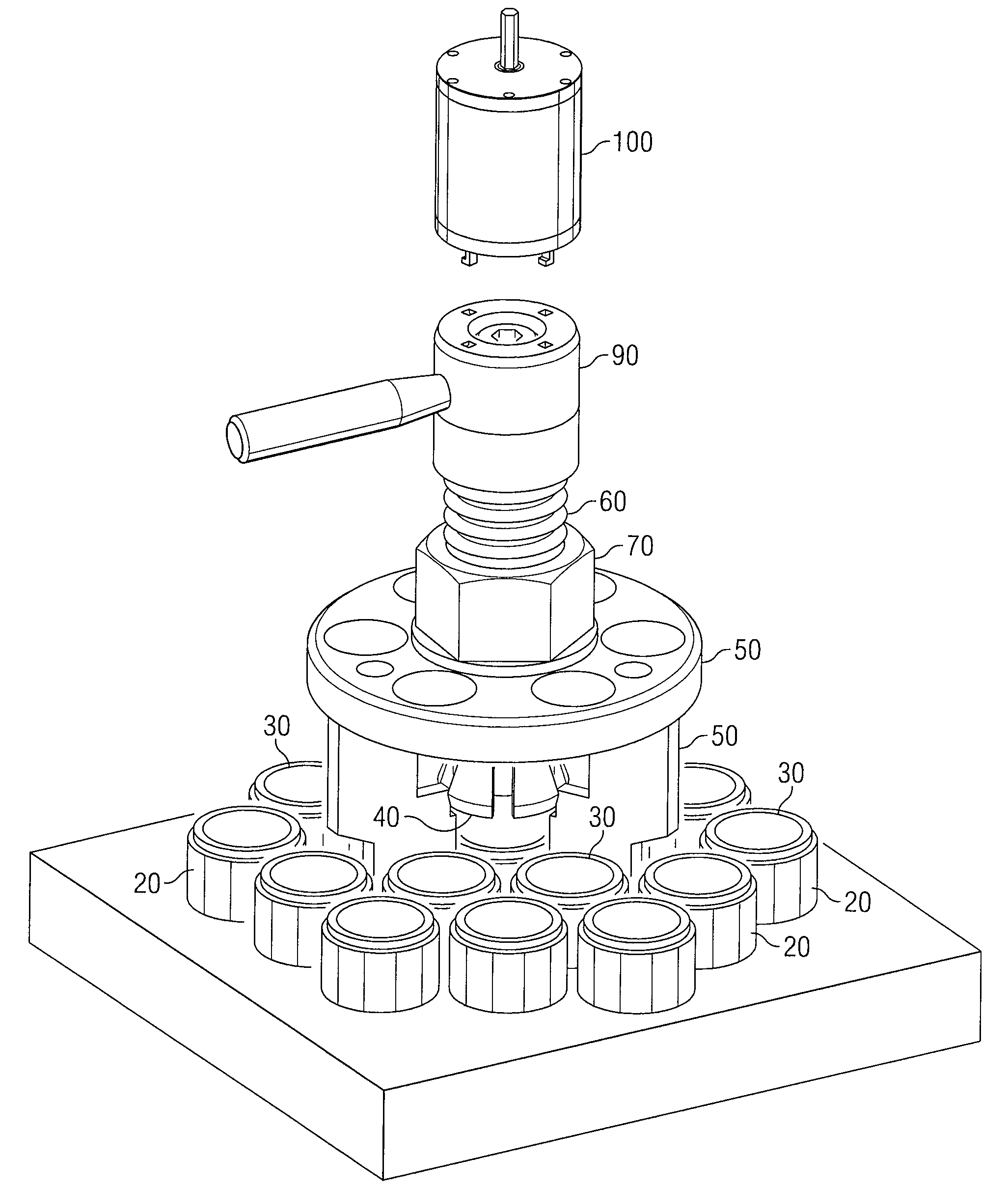
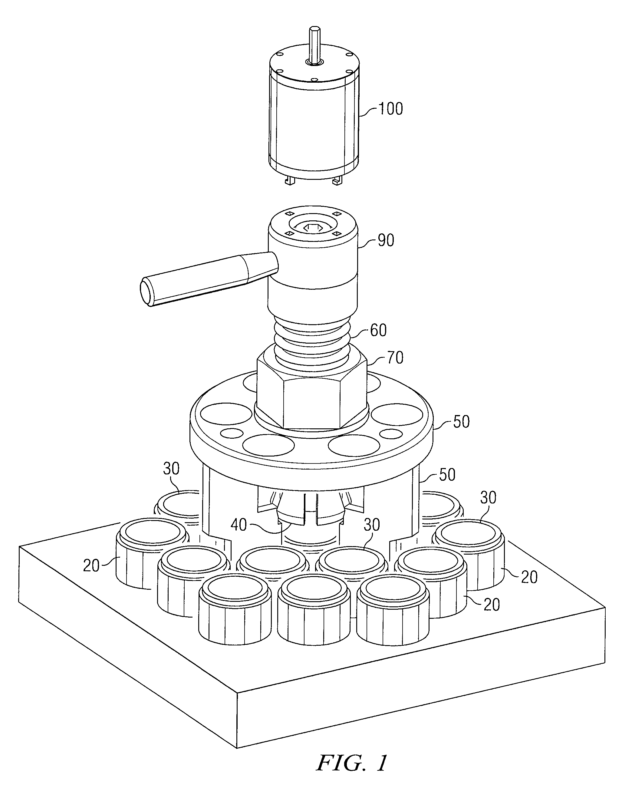
[0012]FIG. 1 illustrates a particular embodiment of a system 10 for extracting seized components. System 10 includes a camlock mechanism 90, a threaded axis 60, a power transfer mechanism 70, a support body 50, a gripping mechanism 40, a vibration mechanism 100, a seized component 30, and a housing 20. To facilitate the extraction of seized component 30, gripping mechanism 40 may be attached to seized component 30. Camlock mechanism 90 may then be rotated to secure gripping mechanism to seized component 30. Additionally, a user may apply a rotational force to a shaft of vibration mechanism 100 to generate a series of vibrations that loosens seized component 30. Then, a user may apply rotational force to power transfer mechanism 70 attached to support body 50 and threaded onto threaded axis 60. The rotational force is translated to linearly force by the interaction of power transfer mechanism 70 on threaded axis 60, and seized component 30 is extracted.

[0013]Housing 20 encloses, in w...


PUM

PropertyMeasurementUnit
Forceaaaaaaaaaa

Abstract

A system and method for extracting seized components is disclosed. The method further grasping a seized component with a gripping mechanism and securing the gripping mechanism to the seized component by turning a camlock mechanism. A force is applied to a power transfer mechanism that moves a threaded axis that is threaded through the power transfer mechanism. The method additionally includes attaching the threaded axis to the gripping mechanism, which extracts the seized component. To facilitate extraction, the method also includes generating vibrations by a vibration mechanism, which may include a vibration mechanism rotating a rotary plate about a shaft. The method may also include generating vibrations by a cam attached to the rotary plate contacting one or more spring-loaded hammers. The spring-loaded hammers may be capable of impacting a strike plate, generating vibrations.

Description

TECHNICAL FIELD OF THE INVENTION[0001]This invention relates generally to mechanical extraction of electronic components and more particularly to a method and system for the extraction of antenna elements in an antenna array.BACKGROUND OF THE INVENTION[0002]In electro-mechanical systems that contain subcomponents, exposure to weather elements can cause various subcomponents to seize to their housings. Particularly problematic are antenna arrays consisting of antenna elements. Antenna arrays are typically exposed to the environment with relatively little protection. Antenna elements and their housings can both be constructed of an aluminum alloy that, when placed in close proximity and exposed to a salt-water atmosphere, can create an aluminum oxide between the element and its housing. This oxidation, combined with natural build-up of particulate matter makes successful damage-free extraction of the antenna elements difficult. Although a protective weather seal may be used to keep mo...

Claims


Application Information

Patent Timeline
IPC IPC(8): B23P19/04
CPCB23P19/04B25B27/02Y10T29/53796Y10T29/53861Y10T29/53848Y10T29/53874
Inventor ROBLEDO, JAIME
Owner RAYTHEON CO
Why Eureka
Try Eureka