Low operating pressure gas scrubber

a gas scrubber and low operating pressure technology, which is applied in the direction of carburetating air, separation processes, chemical/physical/physico-chemical processes, etc., can solve the problems of no prior art device providing a relatively portable device which is capable of cleaning the area, and the present poisonous hydrogen sulfide presents a health risk to workmen in the area

Inactive Publication Date: 2005-05-17
DESERT ENERGY
View PDF25 Cites 32 Cited by
  • Summary
  • Abstract
  • Description
  • Claims
  • Application Information

AI Technical Summary

Problems solved by technology

During such operations, poisonous hydrogen sulfide present presents a health hazard to workmen in the area.
However, none of the prior art devices provide a relatively portable device which is capable of scrubbing gases like hydrogen sulfide from the headspaces of storage tanks or other locations or sources at which the pressure of the gas to be scrubbed exists at a pressure which is only slightly elevated over atmospheric pressure.

Method used


Image

  • Low operating pressure gas scrubber
  • Low operating pressure gas scrubber
  • Low operating pressure gas scrubber

Examples


Embodiment Construction

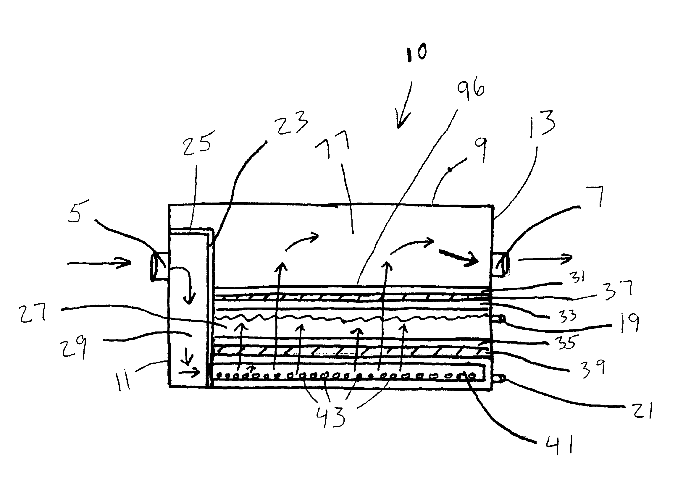
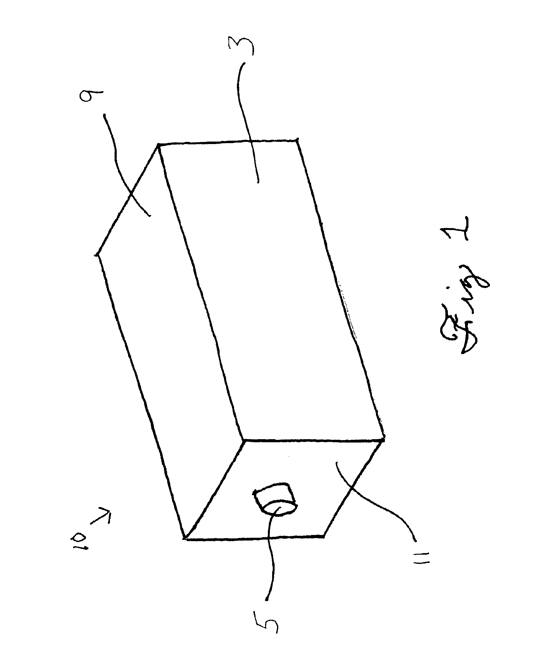
[0036]Referring to the drawings and initially to FIG. 1 there is shown a perspective view of a gas scrubbing apparatus 10 according to the invention existing substantially in the form of a rectangular solid and having a front wall portion 3, top portion 9, left side wall portion 11, and gas inlet hole 5.

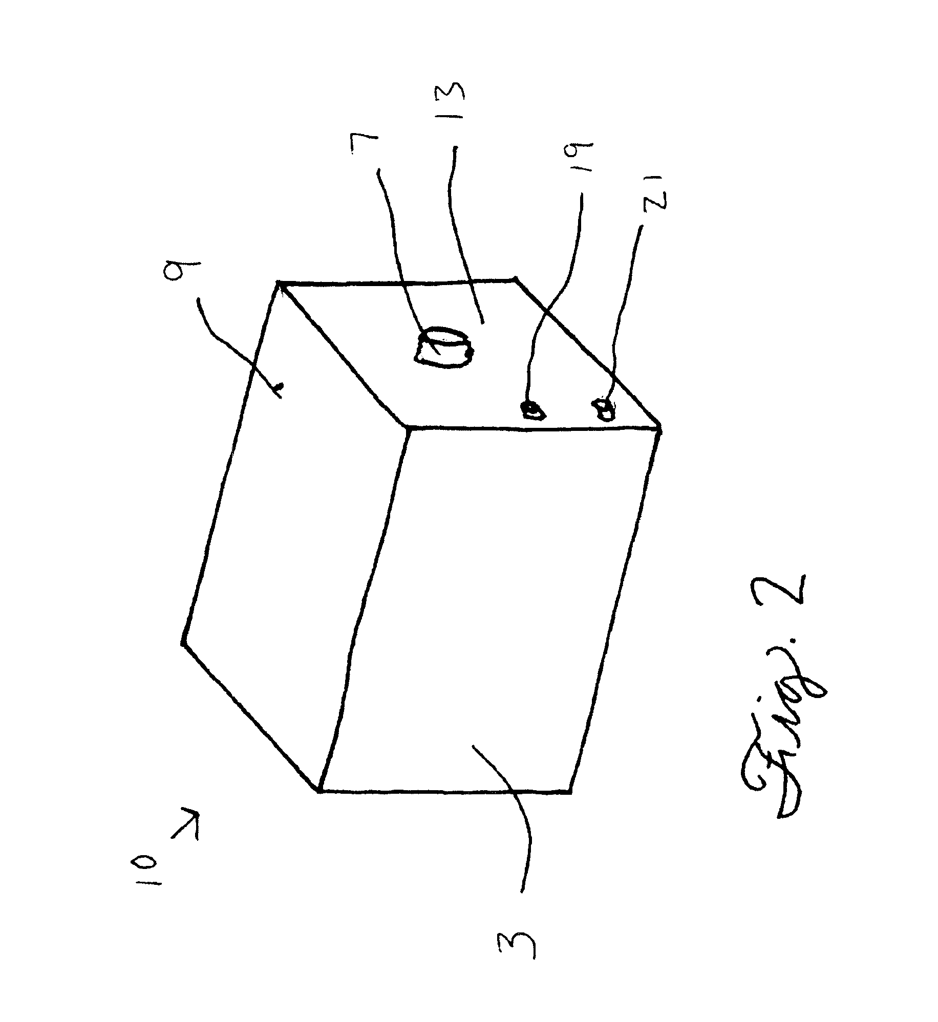
[0037]FIG. 2 shows a perspective view of a gas scrubbing apparatus 10 according to the invention having front wall portion 3, top portion 9, right side wall portion 13, gas outlet hole 7, liquid inlet hole 19, and liquid drain hole 21.

[0038]In FIG. 3 is shown a side view of a gas scrubbing apparatus 10 according to the invention showing the respective locations of the gas inlet hole 5, gas outlet hole 7, liquid inlet hole 19, liquid drain hole 21, and front wall portion 3.

[0039]In FIG. 4A there is shown a perspective view of a gas manifold 69 useful in providing a gas scrubbing apparatus according to the invention, wherein the gas manifold comprises a vertically-disposed plate portio...


PUM

PropertyMeasurementUnit
angleaaaaaaaaaa
angleaaaaaaaaaa
lengthaaaaaaaaaa

Abstract

Provided herein is an apparatus for scrubbing either acidic or alkaline impurities from gas streams, wherein the gas streams to be scrubbed exist at a pressure which is only slightly higher than ambient pressure. An apparatus according to a preferred form of the invention exists substantially in the shape of a rectangular or cubic solid, having an inlet pipe which is directed to an inner chamber having a wall portion which functions as a manifold, including a plurality of gas conduction tubes in fluid contact with the inner chamber, and into which tubes the gas to be scrubbed enters. The gas to be scrubbed passes through holes in the walls of the gas conduction tubes and contacts a liquid absorbent substance present in the interior confines of the apparatus, which liquid is capable of reacting with one or more impurities in the gas stream, thus eliminating the impurities from the gas stream. The gas stream so treated emerges from the apparatus through a gas outlet provision.

Description

TECHNICAL FIELD[0001]This invention relates to gas scrubbing equipment. More particularly it relates to equipment suitable for scrubbing either acidic or alkaline impurities from gas streams, wherein the gas stream to be scrubbed exists at a pressure which is only slightly higher than ambient pressure.BACKGROUND[0002]The prior art is replete with various examples of devices and methods for the removal or “scrubbing” of certain undesirable gaseous components from gas streams in general. One area in which a large number of developments have been made is in the scrubbing of gases produced during oil recovery and storage operations. During such operations, poisonous hydrogen sulfide present presents a health hazard to workmen in the area. To protect the workmen and the public-at-large, the permissible conditions and levels for emissions of hydrogen sulfide are regulated by various regulatory agencies. A few exemplary developments from the prior art follows, each of which are herein inco...

Claims


Application Information

Patent Timeline
Patent Type & Authority Patents(United States)
IPC IPC(8): B01D47/02B01F3/04B01D53/14B01D53/18
CPCB01D53/1456B01D47/021B01D53/18B01D2253/304
Inventor THOMAS, PAUL E.
Owner DESERT ENERGY
Why Eureka
Try Eureka