Control of DC/DC converters having synchronous rectifiers

a technology of synchronous rectifiers and converters, which is applied in the direction of automatic control, process and machine control, instruments, etc., can solve the problems of difficult work, inability to work, and inability to work

Inactive Publication Date: 2005-05-17
SYNQOR
View PDF42 Cites 52 Cited by
  • Summary
  • Abstract
  • Description
  • Claims
  • Application Information

AI Technical Summary

Benefits of technology

[0012]To avoid the problems mentioned above, one solution presented herein is to ensure the synchronous rectifiers and / or the ORing transistors are “disabled” (i.e., kept from turning on) under the conditions that create the problems. Once this is done, output currents can still flow, but only through the uncontrolled rectifiers. These uncontrolled rectifiers prohibit negative current flow, and therefore the problems associated with negative current flow are eliminated.
[0018]In accordance with one aspect of the invention, a DC to DC power converter includes a control circuit which controls the output voltage of the converter. The converter further includes an override control to the control circuit, responsive to a condition of the power converter or connected circuitry, to effect a minimum current limit. Preferably, the power converter includes a synchronous rectifier, and the override control substantially eliminates negative current flow through the controlled rectifier of the synchronous rectifier.
[0019]To effect the minimum current limit, the override control may increase the voltage output of the power converter. The minimum current limit may be a small negative or positive current, and may take the form of a current source, fold-back or fold-forward.

Problems solved by technology

While synchronous rectifiers have been successfully applied in dc / dc converters, a problem arises with their use when two or more dc / dc converters must interact at their output.
A dc / dc converter using controlled rectifiers can draw a negative output current, a result that was not possible when only diode rectifiers were used.
Schemes to enforce current sharing between paralleled converters might solve this problem in the steady state, but they are difficult to make work during “start-up” transients when the converter has been turned on and is switching, but steady-state conditions have not yet reached.
They are also difficult to make work during conditions where one or more converter has gone into a current limit or short-circuit protection.
Often paralleled dc / dc converters with synchronous rectifiers become oscillatory or have other performance problems under these conditions.
Even with the paralleled converters operating in the steady state, they will not share the load current perfectly.
This condition could cause the performance problems mentioned above.
At the very least, it results in an inefficient situation where excess power is circulated among the paralleled dc / dc converters.
Since the controlled rectifier can carry current in both directions when it is turned on, the ORing transistor no longer solves the negative current problem.
Besides paralleled converters, another place where the negative current problem mentioned above comes into play is when connections are made between the outputs of two or more converters to ensure that the difference between their output voltages does not exceed some limit.
The converters may oscillate or otherwise not work correctly under this condition.
Whether converters are connected together at their outputs directly, through ORing transistors, or through clamp diodes, another condition where the negative current problem can arise is when one of the converters is “shut-down.” This shut-down state may be externally commanded through an ON / OFF control input, or it may be the result of the converter's own protection circuitry sensing an abnormal condition such as a voltage, current, or temperature that is too high.
Other conditions not described here may also arise in which a problem is caused by the ability of a dc / dc converter with synchronous rectifiers to draw a negative current.

Method used


Image

  • Control of DC/DC converters having synchronous rectifiers
  • Control of DC/DC converters having synchronous rectifiers
  • Control of DC/DC converters having synchronous rectifiers

Examples


Embodiment Construction

[0053]A description of preferred embodiments of the invention follows.

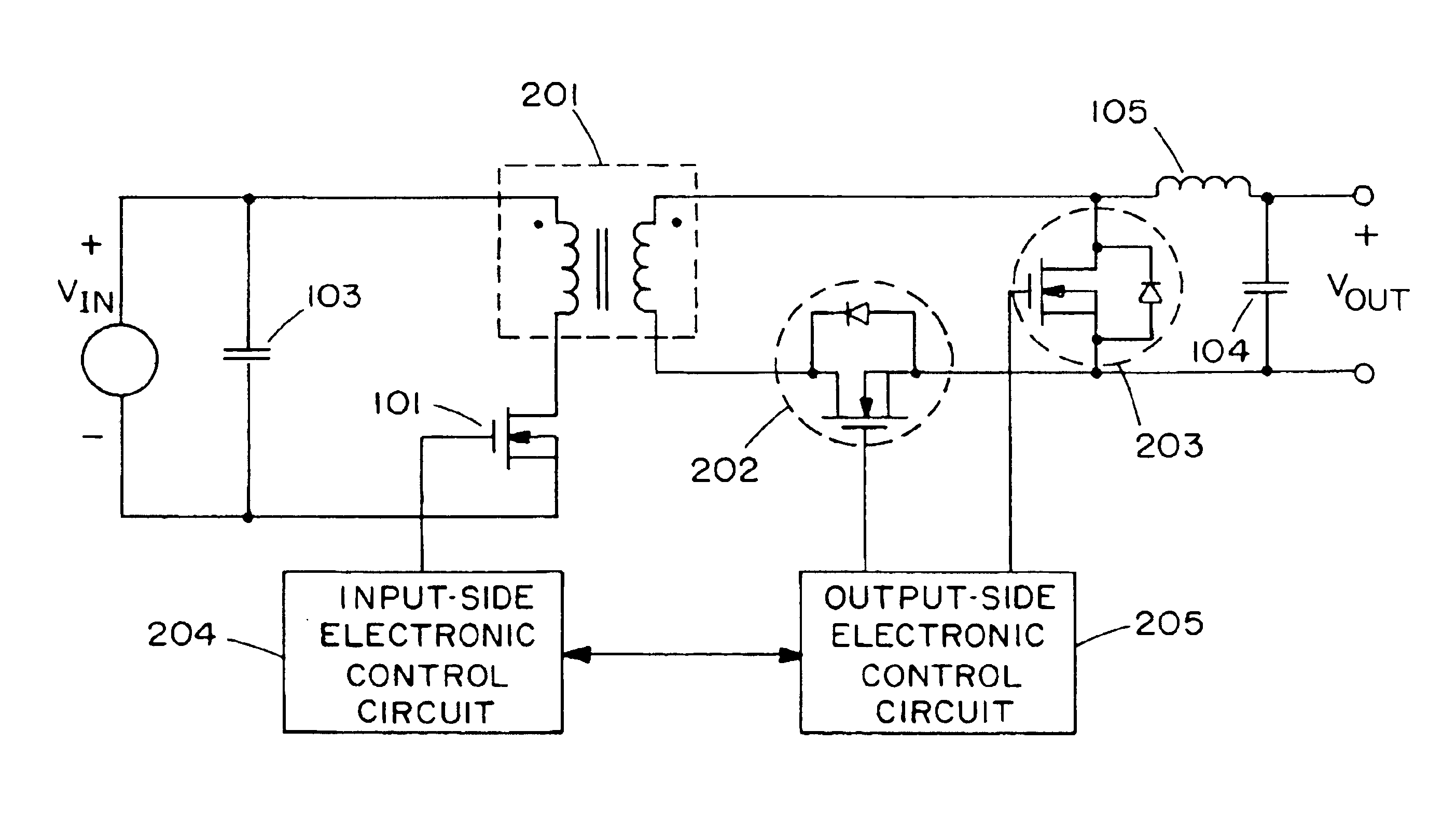
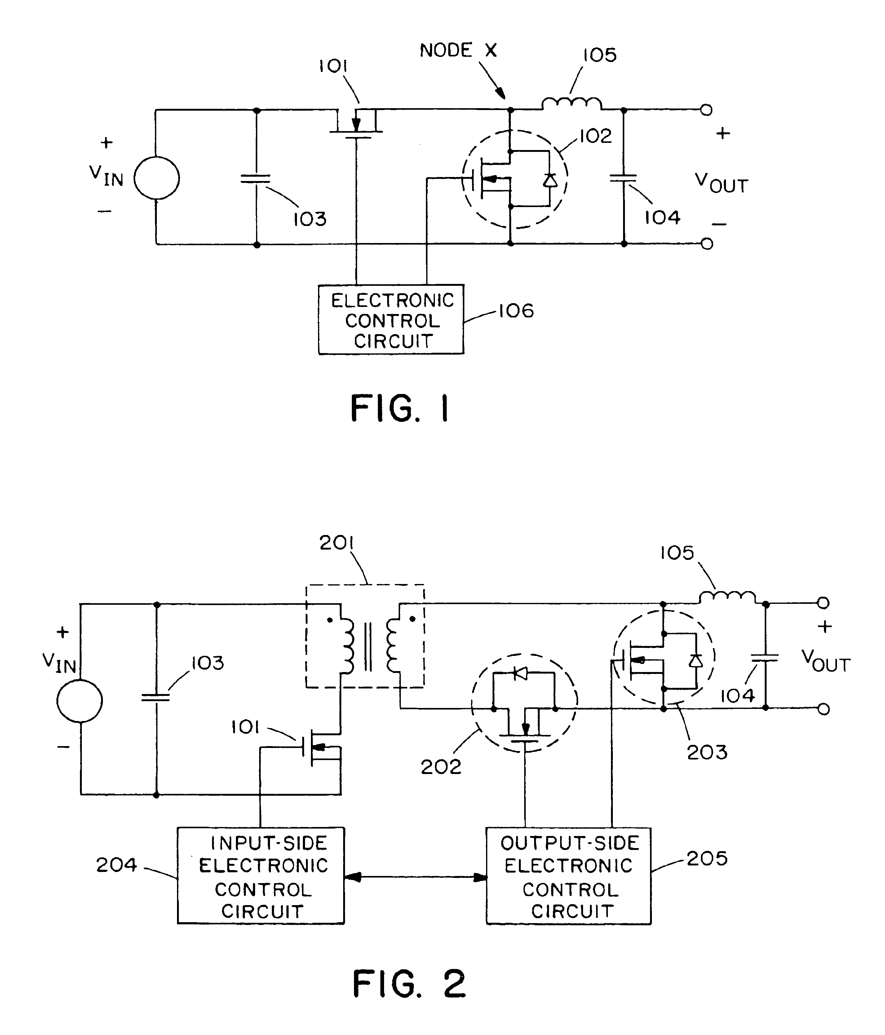
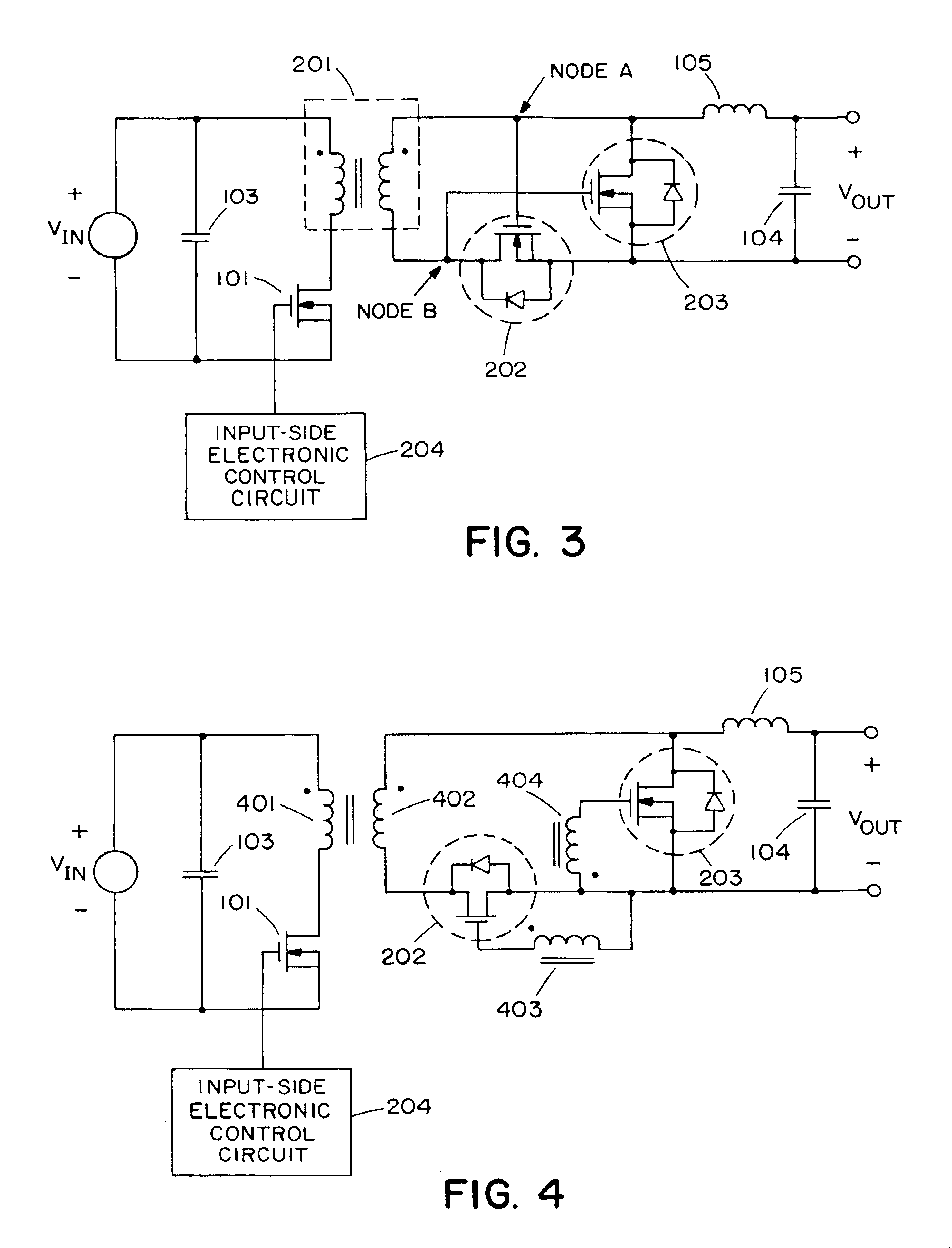
[0054]Throughout this discussion, MOSFETs will be used to implement the synchronous rectifiers and the ORing transistors since the MOSFET is the preferred device at this time. One skilled in the art would know how to incorporate the concepts presented here for other types of transistors that might instead be used.

[0055]When synchronous rectifiers are used in a dc / dc converter, there are two ways to provide the control terminals the signals necessary to turn the controlled rectifiers on and off during the switching cycle. One approach, hereafter referred to as the “active-drive” approach, is to provide the control signal with electronic circuitry that may get its timing information from other electronic circuitry or from voltage or current waveforms within the power circuit. The second approach, hereafter referred to as the “passive-drive” approach, is to provide the control signal either directly or through passiv...


PUM


Abstract

A DC to DC power converter includes synchronous rectifiers which respond to a control waveform. Negative current from a load into the power converter is prevented by increasing the converter output voltage at a minimum current limit. The synchronous rectifiers may be held off in response to decision logic by activation of a hold-off circuit connected to a control terminal of a synchronous rectifier or of an ORing transistor at the converter output. When the synchronous rectifier is subsequently enabled, its control waveform may be increased slowly relative to the switching cycle.

Description

RELATED APPLICATION(S)[0001]This application claims the benefit of U.S. Provisional Application Nos. 60 / 172,884 filed Dec. 20, 1999, 60 / 146,252 filed Jul. 29, 1999, 60 / 143,980 filed Jul. 15, 1999 and 60 / 142,580 filed Jul. 7, 1999, the entire teachings of which are incorporated herein by reference.BACKGROUND OF THE INVENTION[0002]Switching dc / dc converters, whether isolated or non-isolated, have long used a combination of transistors and diodes to implement their switching function. More recently, the diodes have been replaced with transistors called “synchronous rectifiers” for the purpose of reducing the power dissipated by the converter. Typically, MOSFETs are used for the synchronous rectifiers, although other types of transistors such as BJTs and JFETs could also be used. While these transistors can provide a lower on-state voltage than a diode, they do need to be turned on and off at the appropriate times in the switching cycle by the application of a voltage waveform on their ...

Claims


Application Information

Patent Timeline
Patent Type & Authority Patents(United States)
IPC IPC(8): H02M3/158H02M3/04H02M1/00H02M3/335H02M3/24H02J1/10H02M1/32
CPCH02M1/32H02M3/1584H02M3/33592H02J1/102Y02B70/1475H02M1/36Y02B70/10
Inventor BRETZ, JOSHUA H.DANCY, ABRAM P.LAWHITE, LEIF E.SCHLECHT, MARTIN F.
Owner SYNQOR
Why Eureka
Try Eureka