Multi-purpose optical fiber access network

a multi-purpose, optical fiber technology, applied in the direction of multi-plex communication, wireless communication, wavelength-division multiplex system, etc., can solve the problem of difficulty in building an economical access service network

Inactive Publication Date: 2005-05-17
KOREA ADVANCED INST OF SCI & TECH
View PDF3 Cites 168 Cited by
  • Summary
  • Abstract
  • Description
  • Claims
  • Application Information

AI Technical Summary

Benefits of technology

[0030]It is more preferable that the multi-purpose optical fiber access network is composed of: an LMDS / WLL signal modulation / demodulation part for outputting the LMDS signals and WLL signals carried by the carrier to downstream transmission line-after electrically multiplexing them and then modulating them to the first allocated wavelength and for outputting the LMDS signals and WLL signals transmitted through upstream transmission line to the external after converting them to electrical signals; a data signal modulation / demodulation part for outputting the data service signals to downstream transmission line after modulating them to the second allocated wavelength and for outputting the data service signals transmitted through upstream transmission line after demodulating them; a CATV / PCS modulation / demodulation part for outputting the PCS signals and CATV signals carried by the carrier to downstream transmission line after electrically multiplexing them and then modulating them to the third allocated wavelength and for outputting the PCS signals transmitted through upstream transmission line after converting them to electrical signals; a first wavelength division multiplexing part for outputting the signals inputted from said LMDS / WLL signal modulation / demodulation part, said CATV / PCS signal modulation / demodulation part and said data signal modulation / demodulation part after wavelength division multiplexing them and for outputting the signals inputted from upstream transmission line to said LMDS / WLL signal modulation / demodulation part, said CATV / PCS signal modulation / demodulation part and said data signal modulation / demodulation part after demultiplexing them; a first splitting / combining device for outputting the optical powers of the transmitted optical signals while being split after transmitting the optical signals output from the first wavelength division multiplexing part through downstream transmission line; an LMDS / WLL wireless base station for outputting only the first allocated wavelength signals out of the signals inputted from the first splitting / combining device to the wireless line after converting them to electrical signals and for outputting the LMDS signals and WLL signals inputted from the wireless line to upstream transmission line after electrically multiplexing them and then converting them to optical signals; a second wavelength division multiplexing part for outputting the optical signals inputted from the first splitting / combining device after wavelength division demultiplexing them and for outputting the inputted upstream transmission signals to upstream transmission line after wavelength division multiplexing them; a first electrical-to-optical / optical-to-electrical converting part for outputting the optical signals inputted from the second wavelength-division multiplexing part after converting them to electrical signals and electrically demultiplexing them and then modulating the PCS signals to the first allocated wavelength, for outputting the CATV signals after modulating them to the second allocated wavelength, and for outputting the data signals after modulating them to the third allocated wavelength; a second splitting / combining device for outputting the optical signals inputted from the first electrical-to-optical / optical-to-electrical converting part to several output ports after wavelength division multiplexing them and then splitting / combining them and for outputting several optical signals inputted from the external after adding them and then wavelength division demultiplexing them; a second electrical-to-optical / optical-to-electrical converting part for outputting the optical signals inputted from the second splitting / combining device to the second wavelength division multiplexing part after converting them to electrical signals and electrically demultiplexing them and then modulating the PCS signals to the first allocated wavelength and for outputting the cable modem signals and data signals to the second wavelength division multiplexing part after electrically multiplexing them and then modulating them to the second allocated wavelength; a multiplexing device for outputting the optical signals inputted from the second wavelength division multiplexing part and the signals inputted through said LMDS / WLL wireless base station to upstream transmission line after multiplexing them; a third wavelength division multiplexing part for outputting the signals inputted from the second splitting / combining means after demultiplexing them and for outputting the inputted PCS signals, cable modem signals and data service signals to the second splitting / combining device after multiplexing them; a PCS wireless base station for outputting the optical signals inputted from the third wavelength division multiplexing part to wireless line after converting them to electrical signals and for outputting the PCS signals inputted from the wireless line to the third wavelength division multiplexing part after converting them to optical signals; and an optical network unit for outputting the data service signals and CATV signals inputted from the third wavelength division multiplexing part to wired line after converting them to electrical signals and then demodulating them and for outputting the data signals and cable modem signals inputted from the wired line to the third wavelength division multiplexing part after converting each of them to optical signals.

Problems solved by technology

However, in spite of these advantages, vast initial investment cost of equipment for optical device and optical fiber network which are still high cost leads to difficulty in construction of economical access service network.

Method used


Image

  • Multi-purpose optical fiber access network
  • Multi-purpose optical fiber access network
  • Multi-purpose optical fiber access network

Examples


first embodiment

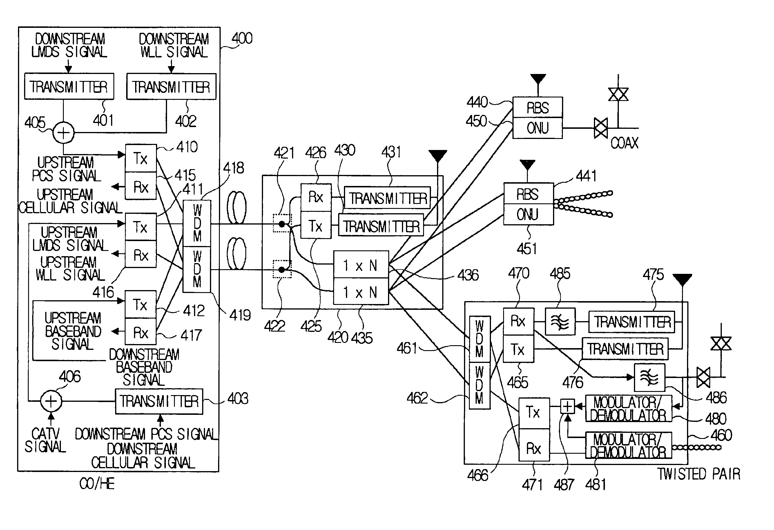
[0104]FIG. 4 is a node block compositional drawing of a multi-purpose optical fiber access network according to the present invention. FIG. 4 shows the case of being composed by using three wavelengths.

[0105]If each wavelength are allocated to each access, the independency of each access service is guaranteed. However lots of light sources are needed to that extent and complicated technology such as wavelength stabilization is also needed. Therefore the construction of economical access network is difficult.

[0106]For the construction of economical access network, the embodiment is the case that provides said access service with three wavelengths by using the first allocated wavelength for LMDS service and WLL service, the second allocated wavelength for CATV service and PCS service and the third allocated wavelength for data service.

[0107]First, in downstream transmission for LMDS service and WLL service wavelength of 1.3 μm, for CATV service and PCS service wavelength of 1.53 μm, a...

second embodiment

[0126]FIG. 5 is a node block compositional drawing of a multi-purpose optical fiber access network according to the present invention. FIG. 5 shows the case of being composed by using five wavelengths.

[0127]The LMDS signal and WLL signal use the same light source and the CATV signal and downstream PCS signal use the same light source in the first embodiment of FIG. 4. Also, the upstream data signal such as the ADSL upstream service and cable modem service uses the same light source in the FIG. 4. From the embodiment of FIG. 4, there is disadvantage that the independency between several access services is not guaranteed.

[0128]The embodiment of FIG. 5 complements the disadvantage by adding two wavelengths.

[0129]In upstream transmission of signal for transmission of LMDS signal wavelength of 1.56 μm, for transmission of WLL signal wavelength of 1.58 μm, for transmission of PCS signal wavelength of 1.54 μm, for transmission of CATV signal wavelength of 1.3 μm and for transmission of dat...

third embodiment

[0142]FIG. 6 is a node block compositional drawing of a multi-purpose optical fiber access network according to the present invention. For LMDS and WLL service one wavelength is allocated, for CATV and PCS service another wavelength is allocated and for transmission of data signal several wavelengths are allocated.

[0143]The difference between the embodiments of FIG. 4 and FIG. 6 is that data signal is transmitted to optical network units 650, 651, 660 by wavelength division multiple access. Accordingly, the central office / headend should equip with N light sources of different wavelengths in order to transmit data signal to N optical network units and each optical unit should equip with wavelength selected distributed feedback laser as light source for transmission of upstream data signal.

[0144]For example, in downstream signal transmission, for LMDS and WLL wavelength of 1.53 μm, for CATV and PCS wavelength of 1.3 μm, and for transmission of data signal wavelength of 1.55 μm is used...


PUM


Abstract

The present invention relates to an optical fiber access network, and more particularly, to a multi-purpose optical fiber access network capable of accepting all services provided by hybrid wireline/wireless access network.
According to the present invention, in an optical fiber access network of double star structure where a central office/headend and several optical network units are connected through a splitting/combining device, a multi-purpose optical fiber access network capable of accepting not only wired telephone service, wired CATV and wired data service but also various kinds of wireless services including LMDS, WLL, PCS and so forth, in which LMDS local wireless base station is located in a place adjacent to the splitting/combining device, WLL local wireless base station is located in a place adjacent to the splitting/combining device, optical network unit connects the conventional wired network composed of said optical fiber access network, twisted pair and coaxial cable, telephone service, data service and CATV service are provided through the optical network unit and PCS local wireless base station is located in a place adjacent to the optical network unit, is provided.

Description

TECHNICAL FIELD[0001]The present invention relates to an optical fiber access network, and more particularly, to a multi-purpose optical fiber access network capable of accepting all services provided by wired network and hybrid wireline / wireless access network.BACKGROUND OF THE INVENTION[0002]Recently confronting information society, the information services needed by each subscriber are becoming various. As a result, not only voice services such as conventional telephone and personal communication service but also analog broadcasting signal service such as cable television and data service such as internet are required.[0003]According as contemporary society is developed to information society, these requirements for communication will be more and more various and still more kinds of services will be required.[0004]Meanwhile, in order to satisfy these needs for communication, communication service providers provide services by using various kinds of methods.[0005]The access networ...

Claims


Application Information

Patent Timeline
Patent Type & Authority Patents(United States)
IPC IPC(8): H04J14/02H04B10/207H04B10/272H04W88/08
CPCH04B10/272H04J14/0226H04J14/0282H04J14/025H04J14/0232H04J14/0246H04J14/0286H04W88/085
Inventor CHUNG, YUN CHURKIM, HOON
Owner KOREA ADVANCED INST OF SCI & TECH
Why Eureka
Try Eureka