
Utensil grip system

a technology for utensils and handles, applied in the field of utensils, can solve the problems of unfavorable user physical constraints, difficult cooking and eating experience, and virtually impossible configuration of utensils for users with limited hand/finger mobility, and achieve the effect of facilitating the gripping and manipulation of utensils

Active Publication Date: 2005-05-24
DINING WITH DIGNITY
View PDF10 Cites 21 Cited by
  • Summary
  • Abstract
  • Description
  • Claims
  • Application Information

AI Technical Summary

Benefits of technology

[0004]Accordingly, it is an object of the present invention to provide a grip system for use with a utensil whereby the grip system facilitates the gripping and manipulation of the utensil.
[0005]Another object of the present invention is to provide a grip system for use with a utensil that can be easily adjusted by a user for optimum performance regardless of the individual user's hand and / or finger strength, mobility and dexterity.

Problems solved by technology

However, for thousands of people, cooking and eating is a challenging experience due to temporary or permanent physical conditions that limit one's hand or finger movement.
Unfortunately, the complexities of configuring this device make such configuration thereof virtually impossible for those who have limited hand / finger mobility or dexterity.
Furthermore, the device's unconventional appearance will most certainly draw attention to its use which, in turn, draws unwanted attention to a user's physical constraints.

Method used


Image

  • Utensil grip system
  • Utensil grip system
  • Utensil grip system

Examples


Embodiment Construction

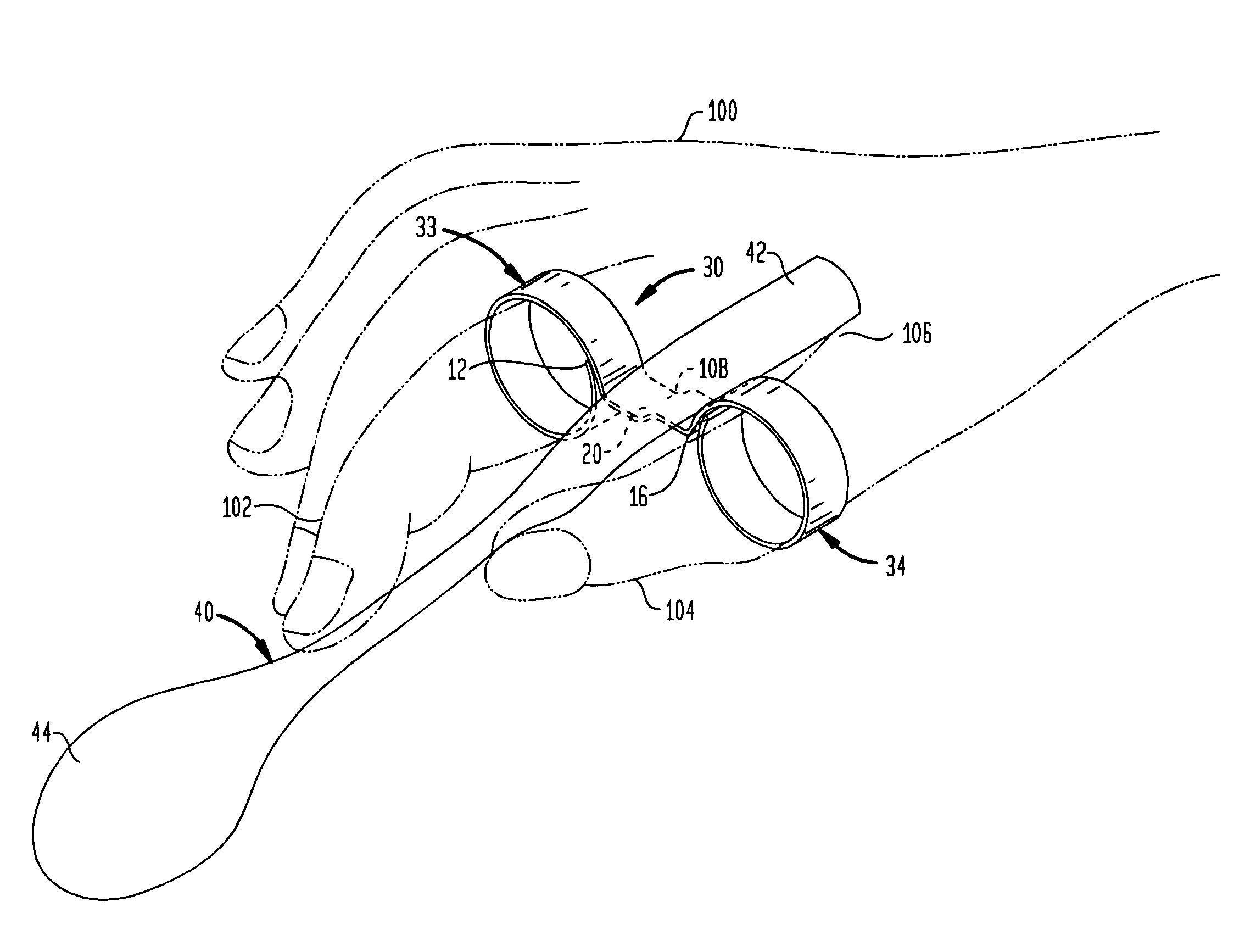
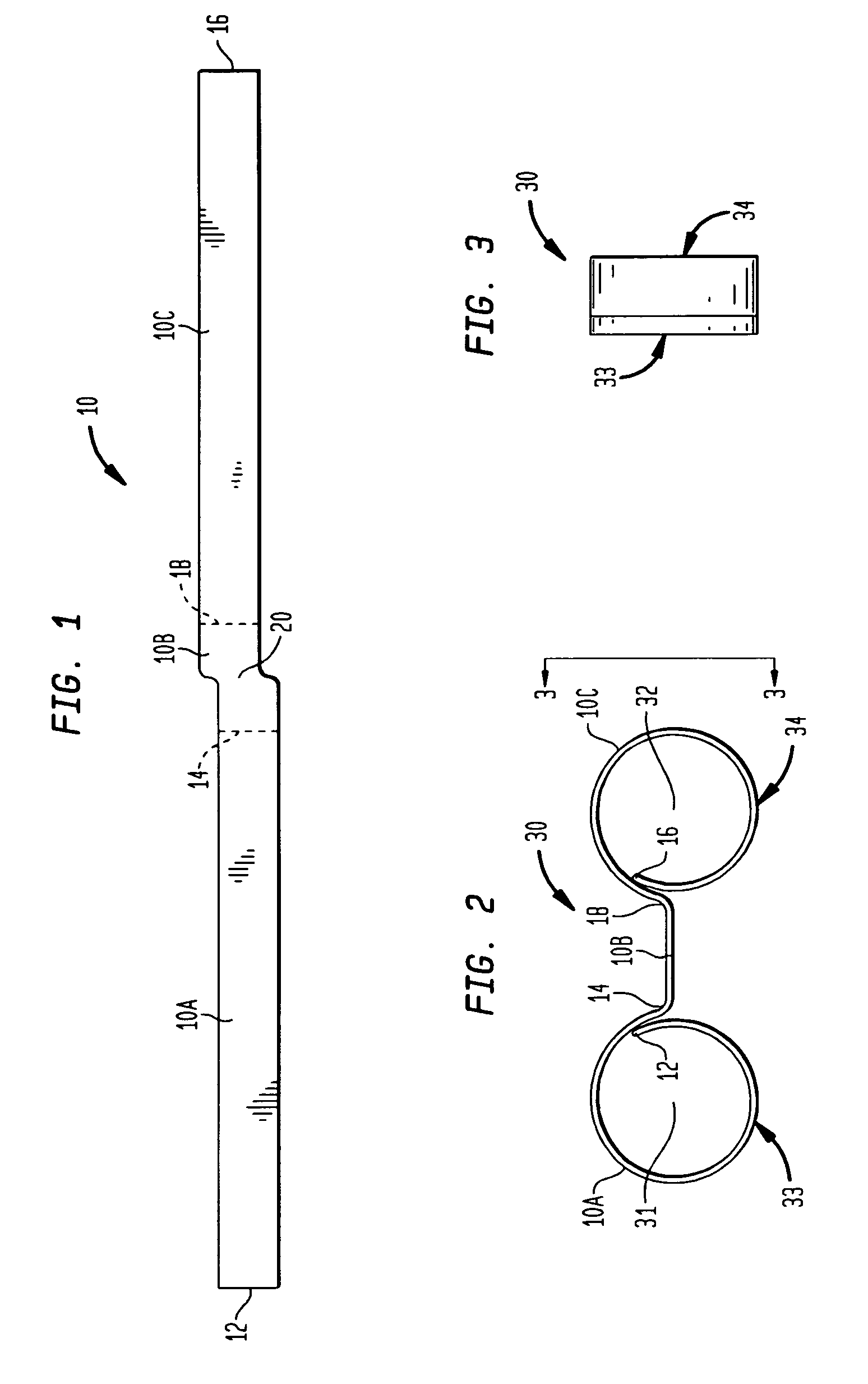
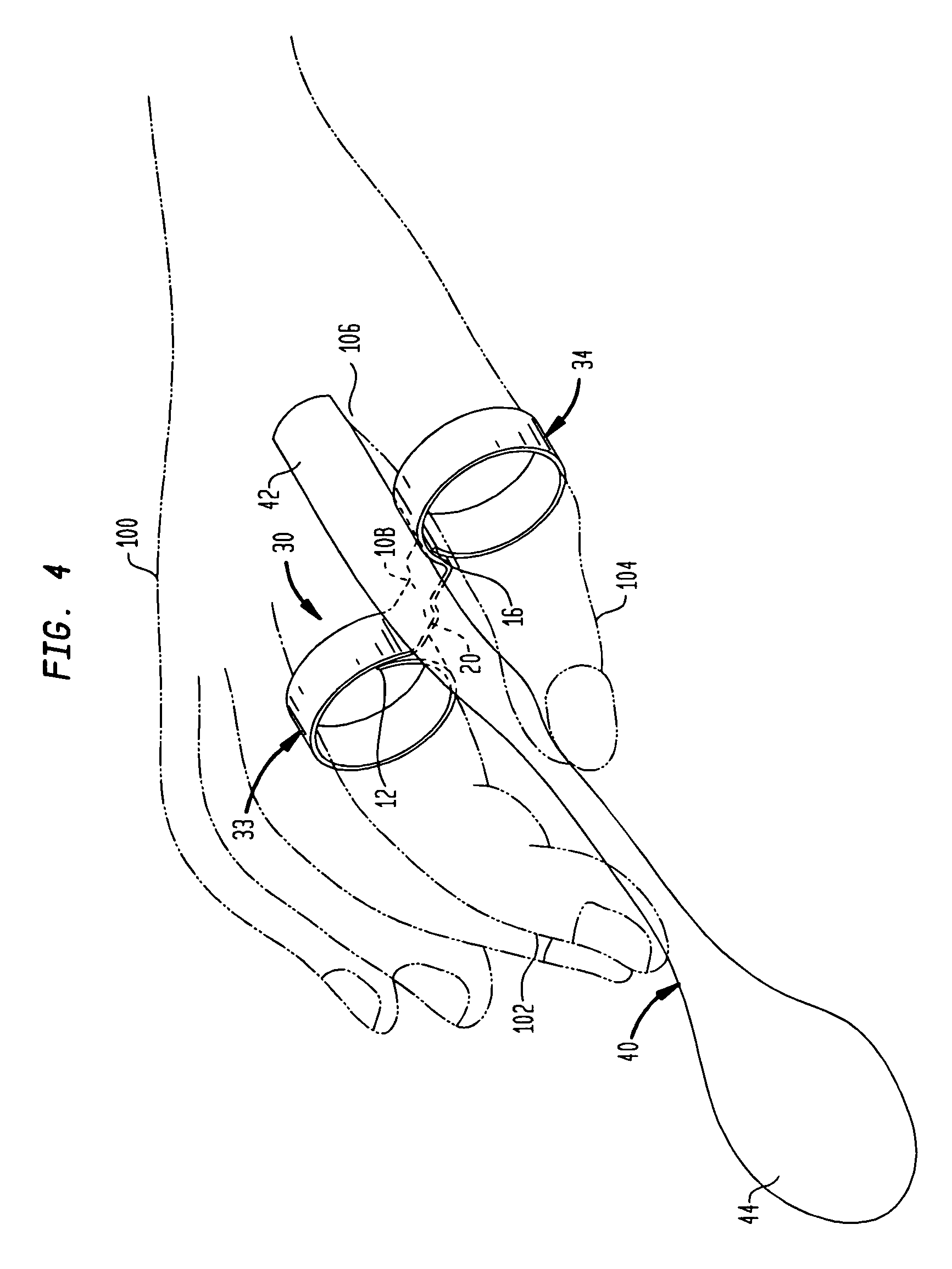
[0017]Referring now to the drawings, simultaneous reference will be made to FIGS. 1–4 where a first embodiment of the grip system of the present invention is depicted in it's raw or pre-shaped form in FIG. 1 and after the shaping thereof in each of FIGS. 2–4. Specifically, FIGS. 2 and 3 are isolated views of the grip system whereas FIG. 4 illustrates the grip system attached to the handle or grip region of a spoon. It is to be understood that utensils other than a spoon (e.g., knife, fork, cooking utensils, etc.) can be used / combined with the grip system without departing from the scope of the present invention.

[0018]In FIG. 1, a single strip of material 10 is shown in its flat or planar configuration. Strip 10 is used as the basis to form the grip system shown in FIGS. 2–4. Strip 10 is defined by a first straight-strip portion 10A, a join portion 10B, and a second straight-strip portion 10C. Straight-strip portion 10A terminates on one end thereof in a free end 12 (of strip 10) and...


PUM


Abstract

A utensil grip system is made from a strip of material defined by a first longitudinal portion terminating in a first free end, a second longitudinal portion terminating in a second free end, and a join region positioned between and coupled to each of the first and second longitudinal portions. The first longitudinal portion is shaped to define a first adjustable-size ring while the second longitudinal portion is shaped to define a second adjustable-size ring. The join region is shaped to offset the first adjustable-size ring with respect to the second adjustable-size ring. The grip region of a utensil is fixedly coupled to the join region.

Description

FIELD OF THE INVENTION[0001]The invention relates generally to utensils, and more particularly to a utensil grip system that facilitates the gripping / manipulation of a conventional utensil using one's thumb and index finger.BACKGROUND OF THE INVENTION[0002]The gripping and manipulation of a utensil (e.g., eating and / or cooking utensils) is an everyday task taken for granted by people without any hand or finger impairment. However, for thousands of people, cooking and eating is a challenging experience due to temporary or permanent physical conditions that limit one's hand or finger movement. Such conditions include, but are not limited to, physical deformities, paralysis or partial paralysis, arthritis, hand or finger injuries, and carpal tunnel syndrome, just to name a few.[0003]A prior art device for assisting a physically handicapped person in the performance of a task managed by the use of one's hands is disclosed in U.S. Pat. No. 6,237,194. Briefly, this reference discloses a d...

Claims


Application Information

Patent Timeline
IPC IPC(8): A45F5/00
CPCA45F5/00Y10T16/476Y10T16/469A61F4/00
Inventor BAYTON, ROBERT L.
Owner DINING WITH DIGNITY
Learn More