Built-in aspirating hood

a built-in, aspirating technology, applied in the field of aspirating hoods, can solve the problems of high evacuation capability, high cost, and ineffective use of free cooking surfaces, and achieve the effect of maximum ergonomics in the use of cooking zones

Inactive Publication Date: 2005-05-24
FABER SPA
View PDF4 Cites 8 Cited by
  • Summary
  • Abstract
  • Description
  • Claims
  • Application Information

AI Technical Summary

Benefits of technology

[0008]In particular, a purpose of the present invention is that of realising an aspirating hood which allows great freedom of movement and which has maximum ergonomics in use of the cooking zone. Indeed, we must tr...

Problems solved by technology

It is effective, but rather awkward, because it is necessary to give particular attention to not banging one's head against the lower edge or the side rims of the aspirating hood and often it is necessary to twist one's body.
This system, whilst offering practicality of use to the cooking surface whi...

Method used


Image

  • Built-in aspirating hood
  • Built-in aspirating hood
  • Built-in aspirating hood

Examples


Embodiment Construction

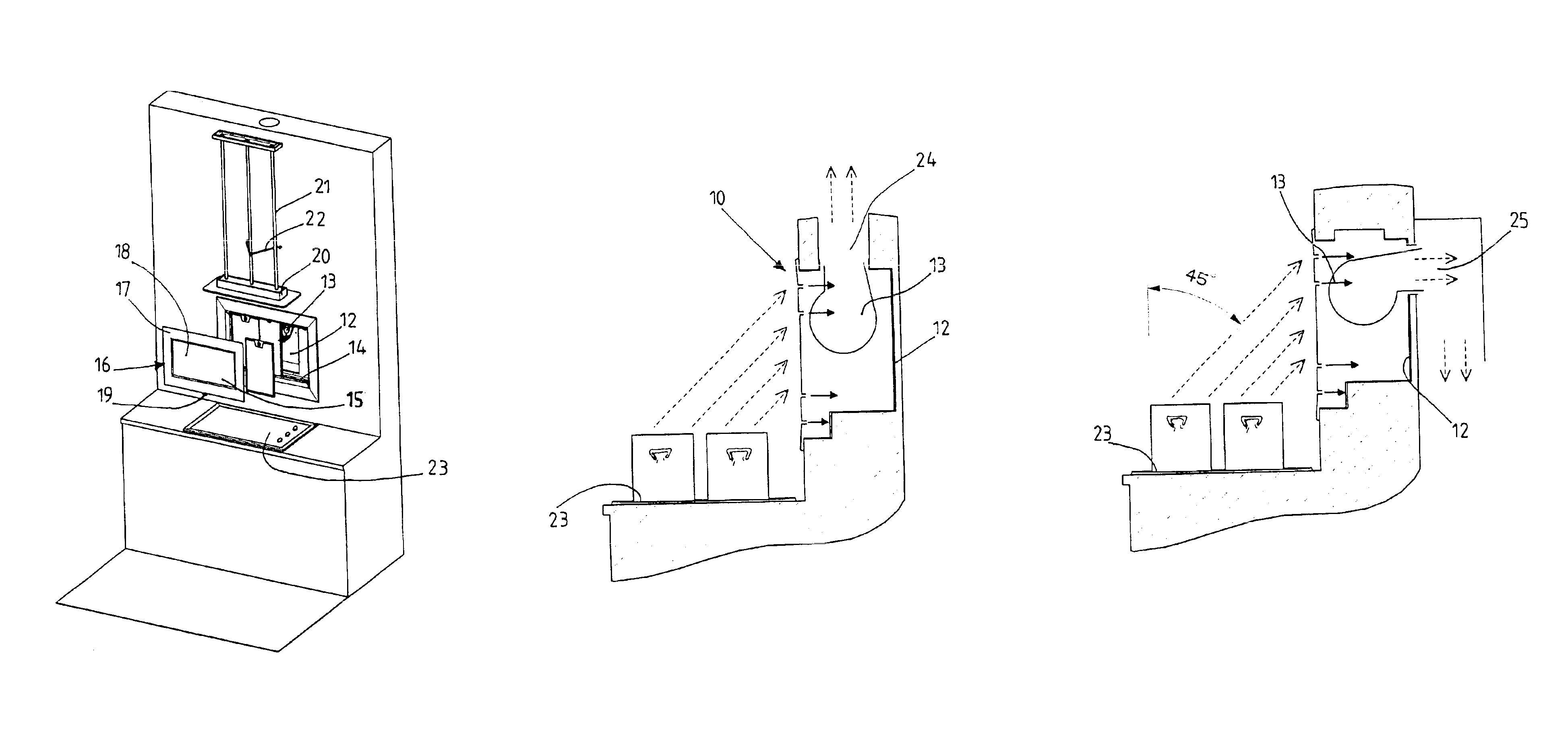
[0016]With reference generically to FIG. 1, an aspirating hood to be built into a wall according to the invention is shown in a totally schematic way, in which the aspirating hood is wholly indicated with 10.

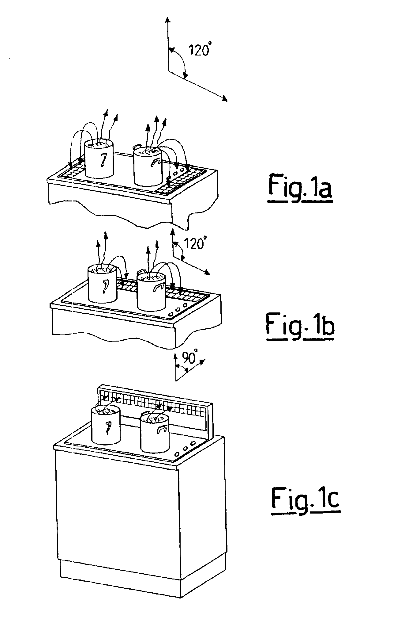
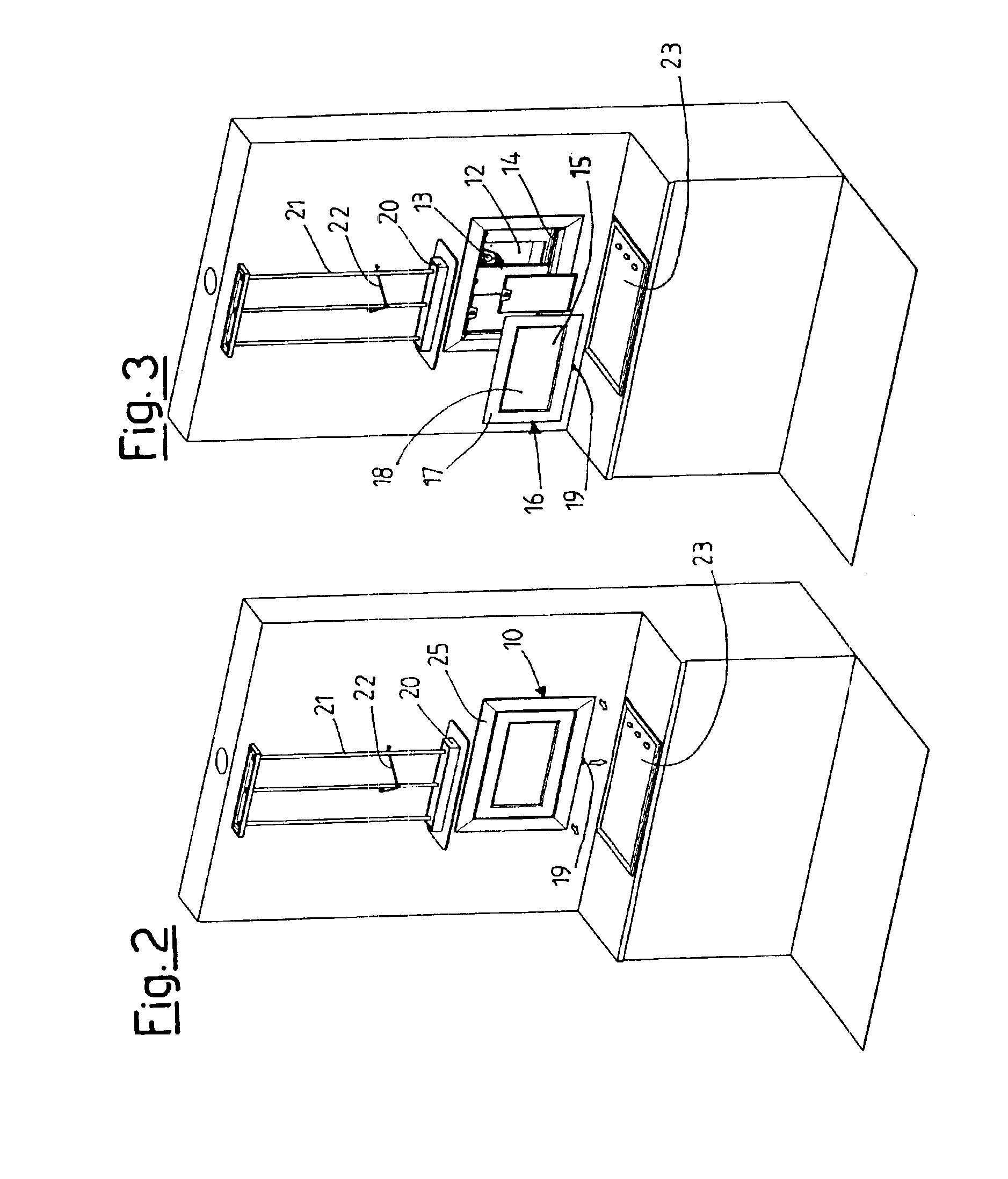
[0017]The built-in aspirating hood 10, which is arranged at a cooking surface 23, consists of a substantially parallelepiped hollow body, preferably made from metal 12, inside of which a centrifugal fan13 is fitted. This fan 13 can be fixed to the body 12 through screws or rapid attachment systems and it usually has the outlet facing upwards, but which can be rotated by 90° to allow an alternative rear outlet. Indeed, the parallelepiped body 12 is equipped with two outlets, one upper 24 and one lower 25, which can alternately be used to evacuate towards the outside the flow of fumes and vapours sucked in by the inner fan 13.

[0018]On the inner perimetric edge of the front face of the parallelepiped body an abutment 14 is formed for one or more anti-fat filters 15, preferably but ...


PUM


Abstract

A built-in aspirating hood which can be applied in a suitable housing in a wall or in furniture, immediately behind a cooking surface and which consists of a parallelepiped body containing a suction fan and a seat for anti-fat filters, the parallelepiped body containing a suction fan and a seat for anti-fat filters. The parallelepiped body is equipped with two outlets, upper and rear, which can alternately be used to evacuate towards the outside the flow of fumes and vapours sucked by the inner fan.

Description

BACKGROUND OF THE INVENTION[0001]The present invention refers to an aspirating hood to be built into a wall.[0002]Currently, aspirating hoods for the kitchen are applied in a variety of ways.[0003]A first way is a small distance above the cooking surface, for example about 65 cm. This is the most widespread installation, because it is the most traditional and the easiest to construct. It is effective, but rather awkward, because it is necessary to give particular attention to not banging one's head against the lower edge or the side rims of the aspirating hood and often it is necessary to twist one's body.[0004]A second way is that on an island at the centre of the room. It is an installation which is similar to the one indicated previously and thus it keeps the advantages and defects thereof.[0005]A third example is that of an aspirating hood integrated in the lower or base furniture. This installation, known and widespread in the USA, going by the name of “down draft” (shown in FI...

Claims


Application Information

Patent Timeline
IPC IPC(8): F24C15/20F24F7/06
CPCF24C15/2042
Inventor GALASSI, ALVARO
Owner FABER SPA
Why Eureka
Try Eureka