Apparatus with automatic respiration monitoring and display

a technology of automatic respiration and display, applied in the field of respiratory systems, can solve the problems of compromising the integrity of monitored signals, requiring high resolution and extensive signal processing, and reducing the need for intervention during the operation of the subject respiratory apparatus, and sacrificing signal integrity. , the effect of reducing or eliminating the need for intervention

Inactive Publication Date: 2005-05-24
RESMED LTD
View PDF14 Cites 39 Cited by
  • Summary
  • Abstract
  • Description
  • Claims
  • Application Information

AI Technical Summary

Benefits of technology

[0014]A key advantage of the invention to a clinician performing a sleep study is that the need for intervention during the operation of the subject respiratory apparatus is reduced or eliminated. The present invention simplifies respiration monitoring without sacrificing signal integrity.
[0015]A further advantage of the subject invention is that it provides a respiratory apparatus which displays a respiration signal as an indication of the upper airway resistance in a patient, the apparatus being reliable and easy to use.
[0016]Other objectives and advantages of the invention shall become apparent from the following description.
[0017]Briefly, a respiratory apparatus constructed in accordance with this invention includes a blower providing a flow of pressurized air to the patient, a patient interface (such as a mask receiving air from the blower), a control unit for managing the blower, and a display...

Problems solved by technology

This technique can be unsatisfactory because: (1) if the high-pass filter excludes low-frequency components of the respiratory signal, it will compromise the integrity of the monitored signal; (2) it is slow to track changes in CPAP component, particularly fluctuations due to leaks which are often known to cause step changes in the pressure signal; and (3) if performed in software, it requires high resolution and extensive signal processing.
The disadvantage of a DC-coupled technique is that the CPAP component appears as a DC offset which must be subtracted from the complex ...

Method used


Image

  • Apparatus with automatic respiration monitoring and display
  • Apparatus with automatic respiration monitoring and display
  • Apparatus with automatic respiration monitoring and display

Examples


Embodiment Construction

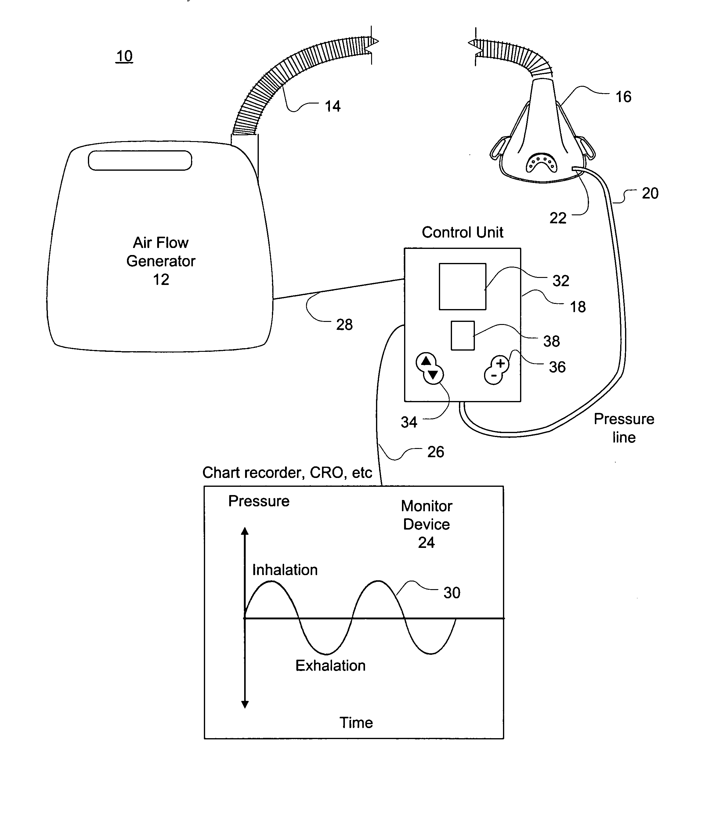
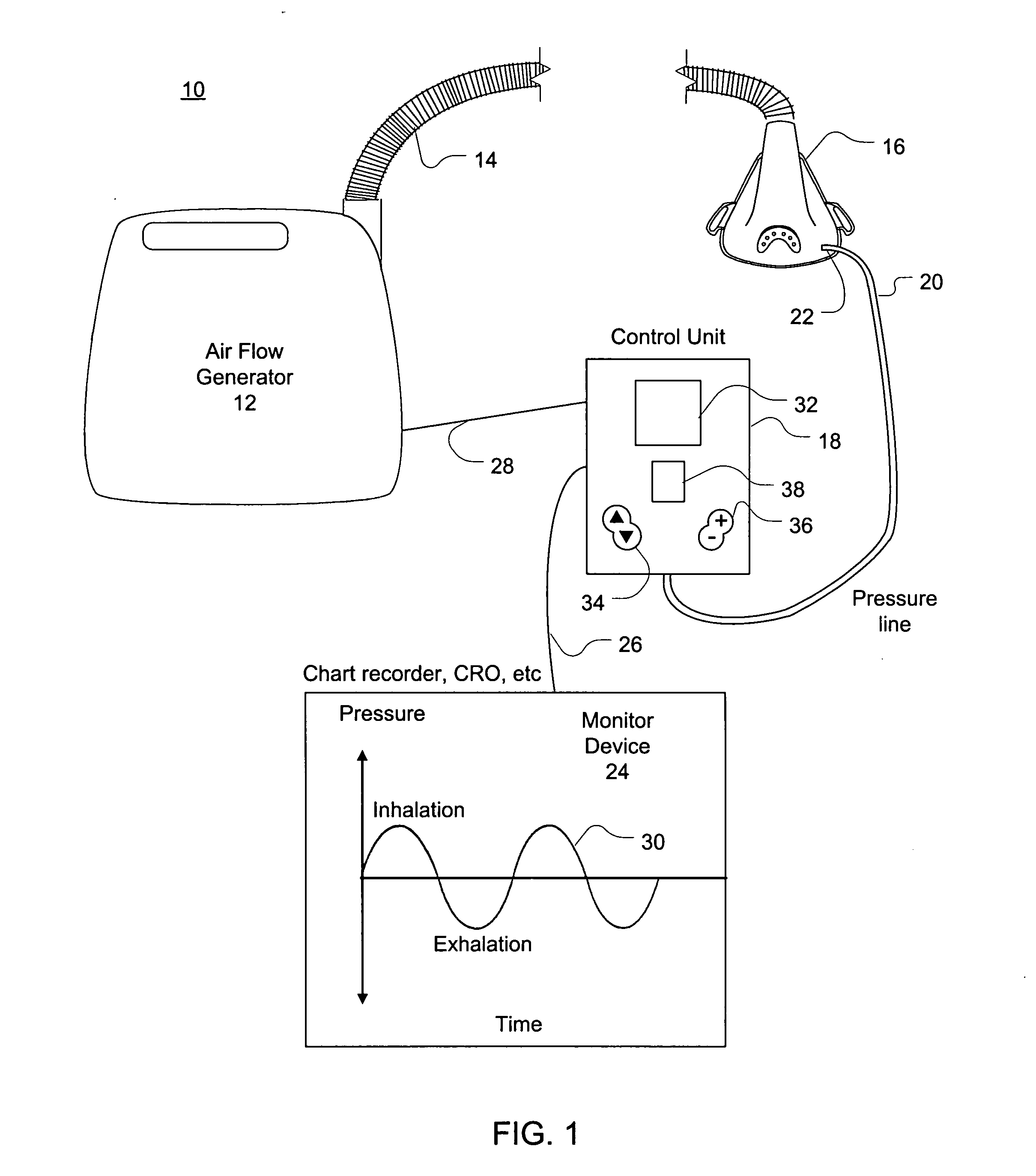
[0022]Referring now to FIG. 1, a respiratory apparatus 10 constructed in accordance with this invention includes a blower 12 adapted to provide pressurized air, a flexible conduit 14, a mask 16 and a control unit 18. The control unit 18 is connected to the mask 16 by a flexible pressure line 20 via a pressure port 22. The control unit 18 is also connected to a display 24 and to the blower 12 by respective cables 26 and 28. The blower 12 may be a CPAP flow generator such as the one marketed under the name Sullivan®V generator made by ResMed Ltd. of North Ryde, NSW, Australia.

[0023]The mask 16 is used to represent generically any suitable patient interface such as a nasal mask or a full face mask, such as the Mirage® mask made by ResMed, or other similar devices designed to deliver air from the generator 12.

[0024]The display 24 is designed to indicate graphically the operation of the apparatus 10 and the respiration of the patient, as indicated, for example, on chart 30. The display 2...


PUM


Abstract

A respiratory device is provided with a display showing a respiration signal related to a breathing pattern of a patient. This signal is derived from the difference between a sensed signal indicative of the respiration and airflow generated by the device and a baseline signal. The parameter is adjusted so that the respiration signal is restricted to a predetermined dynamic range. A short term average of the respiration signal (taken over about 0.5 seconds) and a long term average of respiration signals (taken over about 12 seconds) are calculated based on the CPAP measure. These averages are used to monitor the dynamic change in the respiration signal. If a large variation in either average is detected, the baseline is set to a value selected to rapidly reduce the respiration signal to a lower offset.

Description

[0001]This application claims priority to U.S. provisional application Ser. No. 60 / 139,516 filed Jun. 16, 1999.BACKGROUND OF THE INVENTION[0002]A. Field of Invention[0003]The invention relates to respiratory systems such as Non-Invasive Positive Pressure Ventilation (NIPPV), nasal Continuous Positive Airway Pressure (CPAP) and other similar apparatus, used, for example, in the treatment of Sleep Disordered Breathing (SDB) or Obstructive Sleep Apnea (OSA). More particularly, this invention pertains to a respiratory apparatus which uses an automatic baseline tracking technique to monitor and display a patient's respiration, for example during a CPAP titration session of a sleep investigation.[0004]B. Description of the Prior Art[0005]CPAP, NIPPV and similar types of respiratory apparatus function to supply clean breathable gas (usually air, with or without supplemental oxygen) at a prescribed pressure or pressures, synchronously with a patient's respiration. A suitable CPAP apparatus ...

Claims


Application Information

Patent Timeline
IPC IPC(8): A61M16/00A61M16/06
CPCA61M16/00A61M16/0066A61M2205/52A61M2016/0021A61M16/06A61M16/0069A61M16/024
Inventor MARTIN, DION CHARLES CHEWESMITH, JEFFREY PETER
Owner RESMED LTD
Why Eureka
Try Eureka