Belt connector and method

a technology of belt connectors and belt loops, which is applied in the direction of transportation and packaging, mechanical equipment, ropes and cables for vehicles/pulleys, etc., can solve the problems of thread pulling from the laundry being transported on the conveyor belt, damage to the belt connectors, and a tendency to break the belt connector,

Inactive Publication Date: 2005-05-24
MATO MASCH & METALLWARENFABRIK CURT MATTHAEI GMBH & CO KG
View PDF40 Cites 12 Cited by
  • Summary
  • Abstract
  • Description
  • Claims
  • Application Information

AI Technical Summary

Benefits of technology

[0027]The invention therefore suggests a specifically designed belt connector with a specifically positioned cover element which not only protects essential areas of the wire hooks, but also protects the goods being transported on the belt, and also adds traction from the cover element. This is the case when force from the cover element is conducted into the cross wire connecting the wire hooks. The cover elements pro

Problems solved by technology

Heretofore, such belt connectors have had a tendency to break, particularly if the belt is run in a type of dip or non-linear fashion, or must pass through a number of deflection rollers.
Furthermore, damage can occur where one or more of the wire hooks break and protrude beyond the conveying surface of the belt, even when the lacing includes a reinforcing cross wire to interconn

Method used


Image

  • Belt connector and method
  • Belt connector and method
  • Belt connector and method

Examples


Embodiment Construction

[0037]For purposes of description herein, the terms “upper”, “lower”, “right”, “left”, “rear”, “front”, “vertical”, “horizontal” and derivatives thereof shall relate to the invention as oriented in FIGS. 1 and 2. However, it is to be understood that the invention may assume various alternative orientations and step sequences, except where expressly specified to the contrary. It is also to be understood that the specific devices and processes illustrated in the attached drawings, and described in the following specification, are simply exemplary embodiments of the inventive concepts defined in the appended claims. Hence, specific dimensions and other physical characteristics relating to the embodiments disclosed herein are not to be considered as limiting, unless the claims expressly state otherwise.

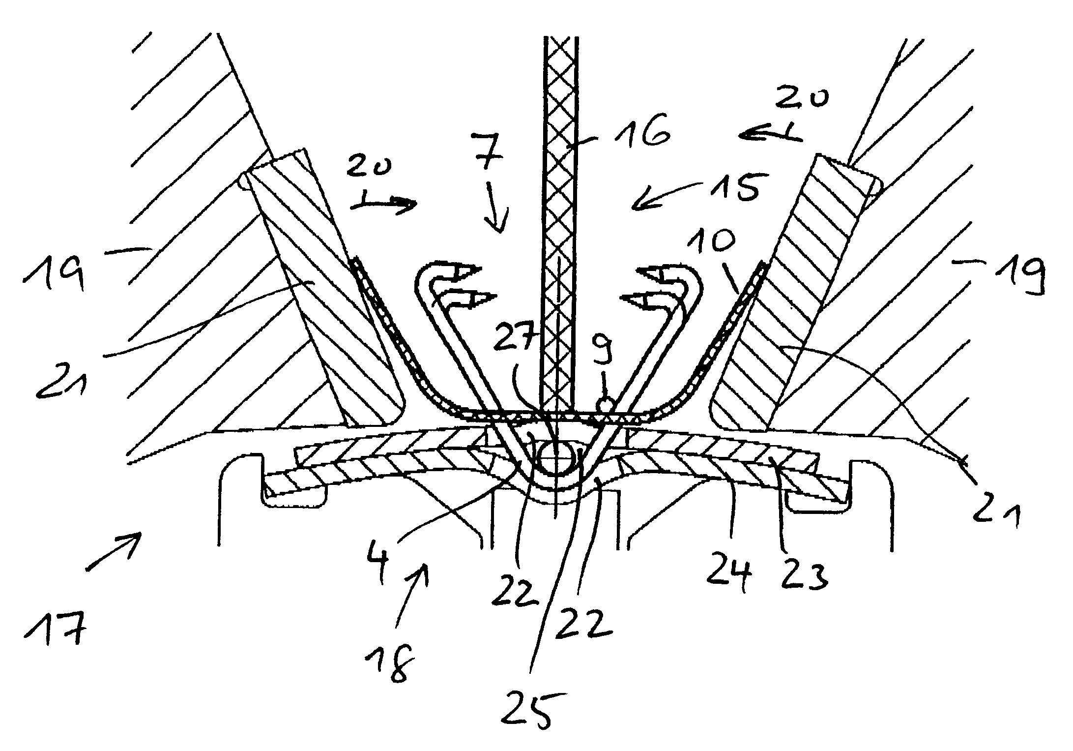
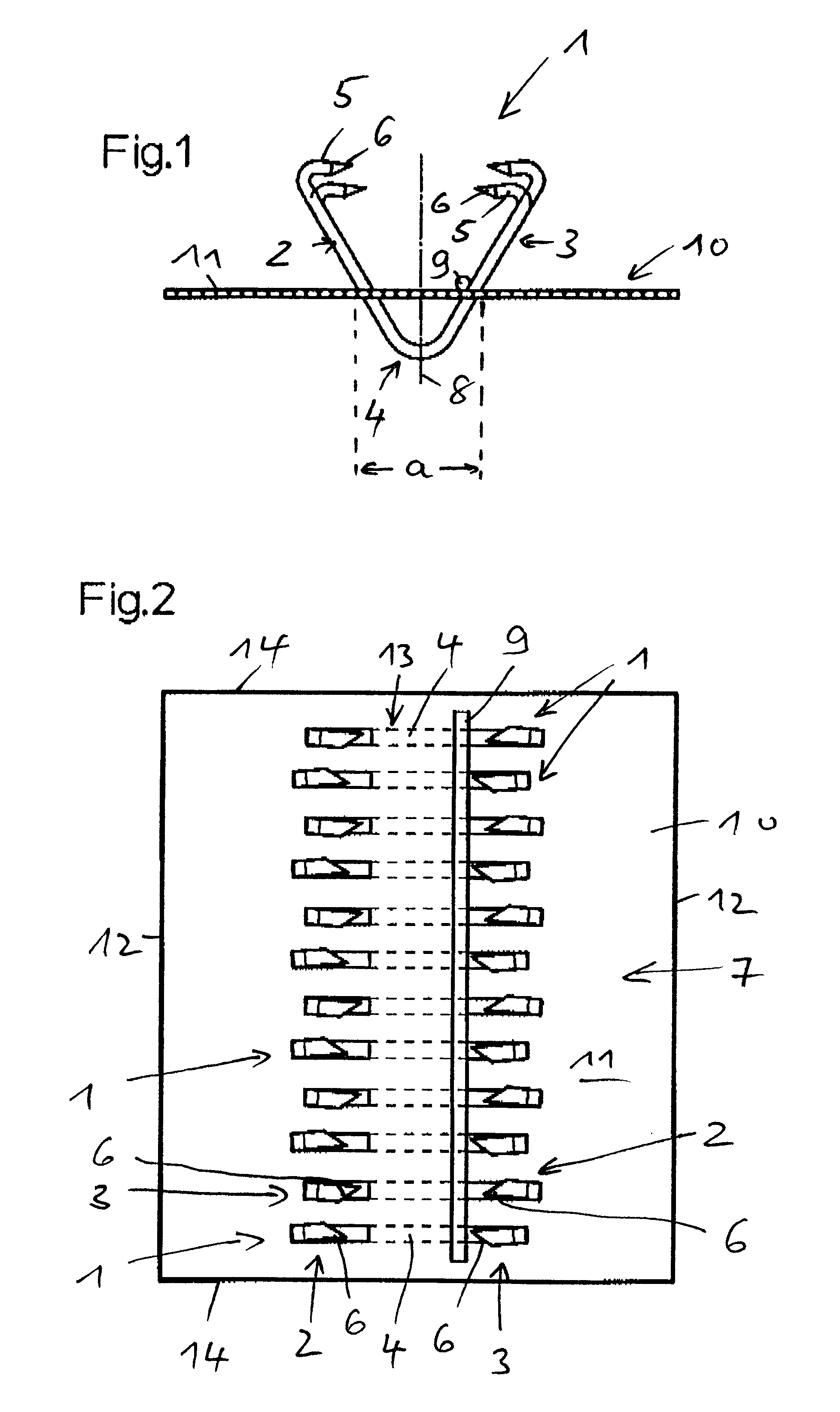
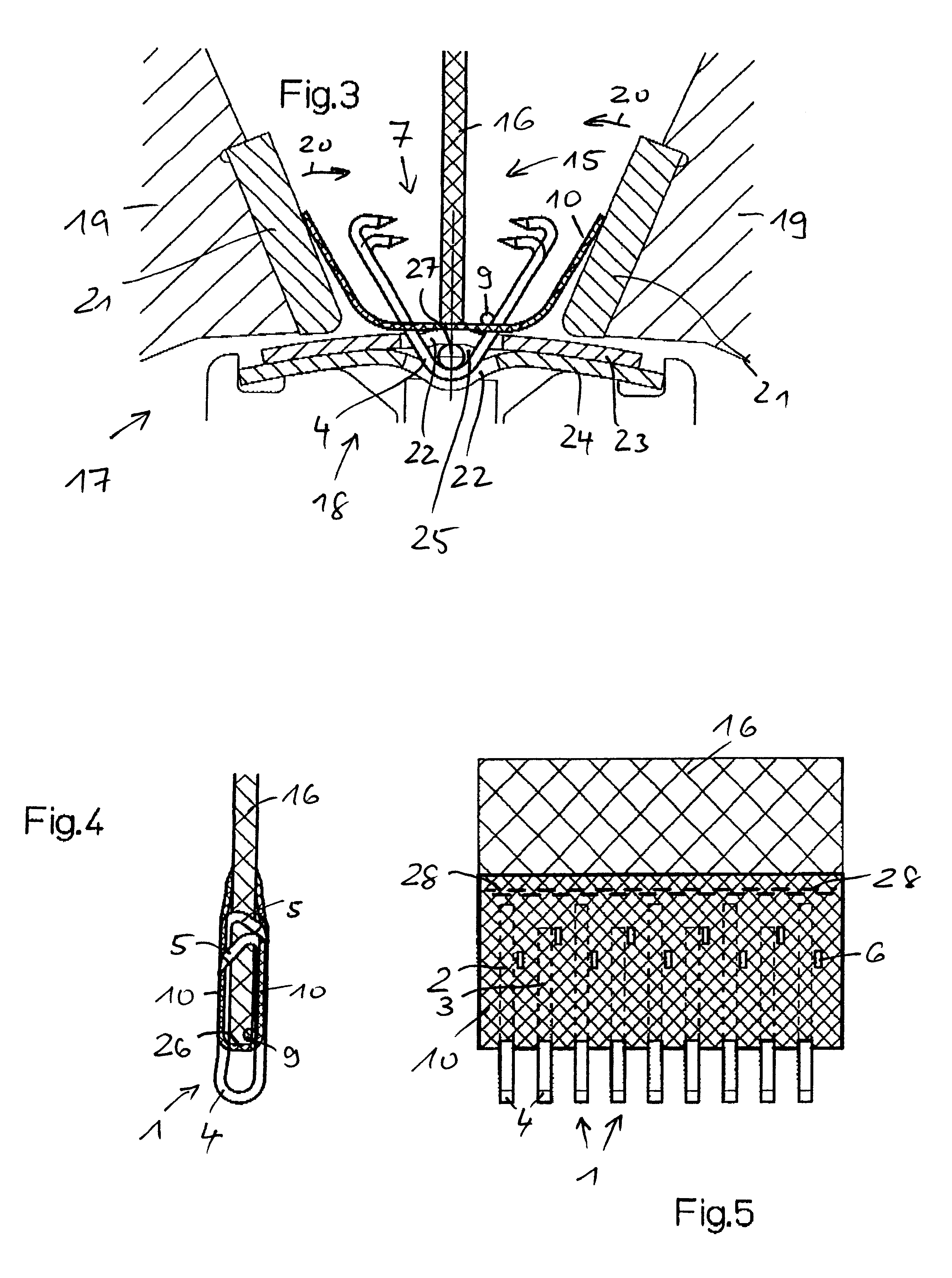
[0038]In the illustrated example, connection element 1 is in the nature of a wire hook, which has a long shank 2, and a short shank 3, as well as a coupling loop 4 which connects shanks 2...


PUM


Abstract

A connector for conveyor belts and the like includes a plurality of connection elements disposed in a side-by-side relationship to extend across the end edge of an associated belt. Each of the connection elements includes outwardly disposed shank portions with free ends shaped for insertion into the opposite faces of the belt, and inwardly disposed loop-shaped center portions arranged to mesh with a like connector on the opposite end of the belt. A generally flat cover element has a central aperture through which the center portions of the connection elements are inserted, and is deformable for folding the cover element over the end edge of the belt and onto the opposite faces of the belt to cover the shank portions of the connection elements on both sides of the belt.

Description

CLAIM OF PRIORITY[0001]Applicant hereby claims the priority benefits under the provisions of 35 U.S.C. §119, basing said claim of priority on European Patent Application Serial No. 02 003 477.3, dated Feb. 14, 2002. In accordance with the provisions of 35 U.S.C. §119 and Rule 55(b), a certified copy of the above-listed European patent application will be filed before grant of a patent.BACKGROUND OF THE INVENTION[0002]The present invention relates to belting, such as conveyor belts and the like, and in particular to a belt connector and method.[0003]As disclosed in German Patent Document DE 198 20 204 A1, belt connectors or lacings are generally well known in the art, and include wire hook type fasteners which are pressed into the opposite ends of the belt, and have generally U-shaped coupling loops which mesh with the coupling loops on a similar connector on the opposite end of the belt. A coupling rod is inserted through the coupling loops in the meshed or overlapping area to creat...

Claims


Application Information

Patent Timeline
IPC IPC(8): F16G3/00F16G3/04
CPCF16G3/04Y10T24/162Y10T24/1608
Inventor HEROLD, WOLFGANG
Owner MATO MASCH & METALLWARENFABRIK CURT MATTHAEI GMBH & CO KG
Why Eureka
Try Eureka