

Arcuate dynamic lordotic guard with movable extensions for creating an implantation space posteriorly in the lumbar spine
a dynamic lordotic guard and lumbar spine technology, applied in the field of lumbar spine implantation space posteriorly, can solve the problems of difficult removal of distractor elements, and achieve the effect of convenient insertion and removal, quick spacing apart and positioning, and effective and accurate spacing and positioning
- Summary
- Abstract
- Description
- Claims
- Application Information
AI Technical Summary
Benefits of technology
Problems solved by technology
Method used
Image

Examples
Embodiment Construction
[0055]Reference will now be made in detail to the present preferred embodiments of the invention, as illustrated in the accompanying drawings.
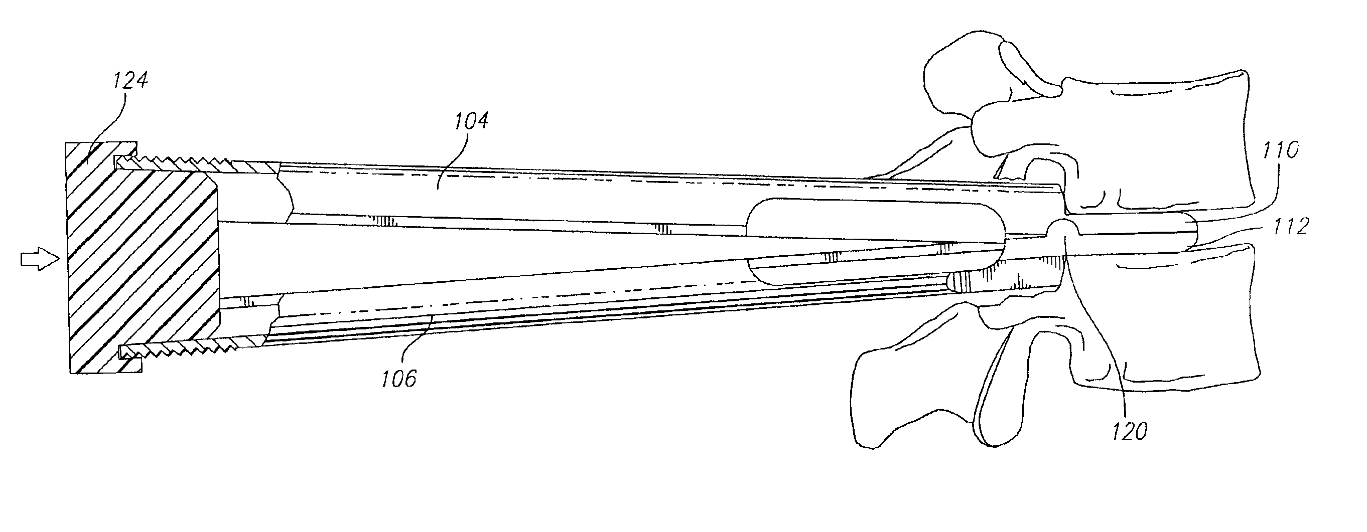
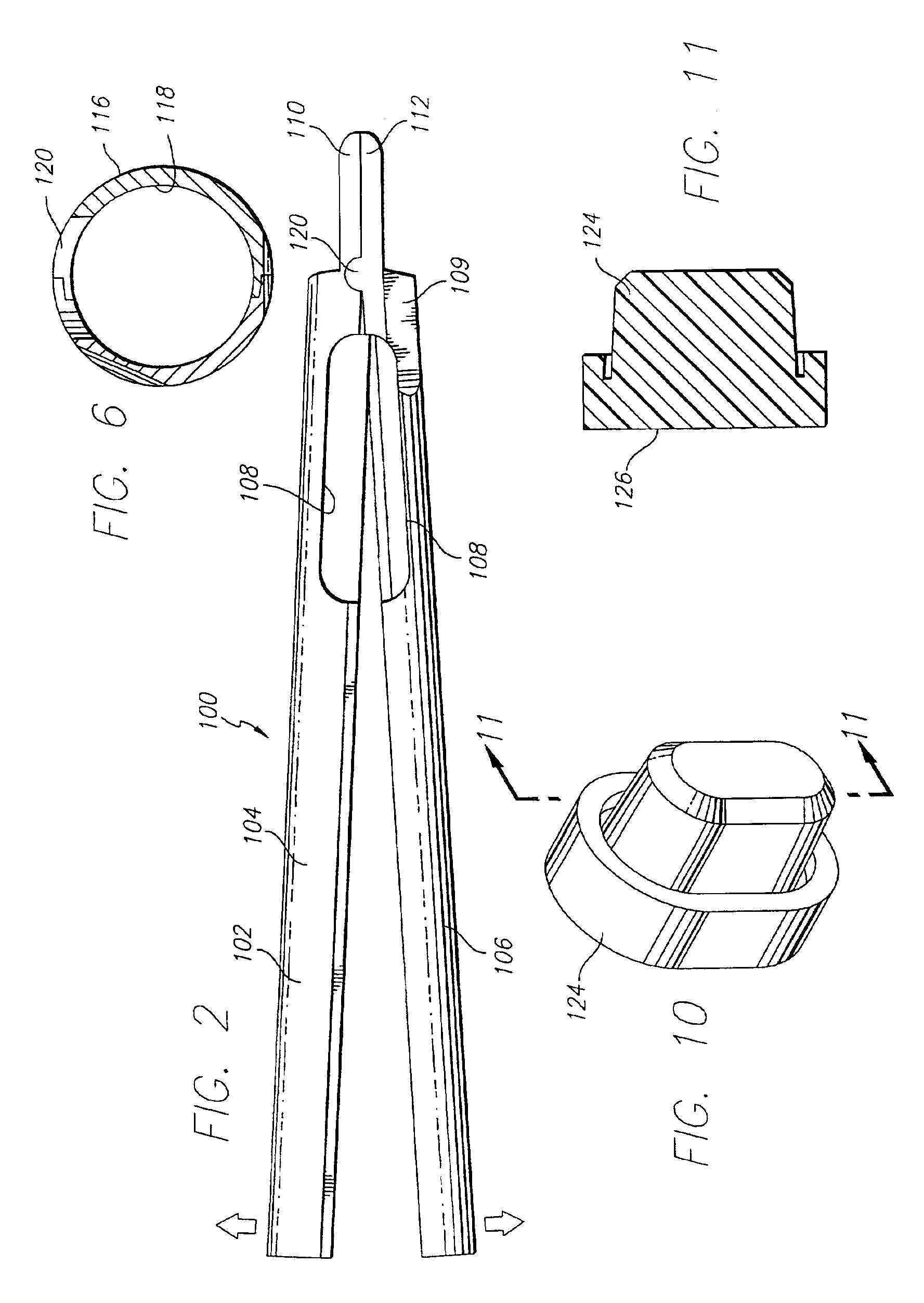
[0056]FIGS. 2-5 are generally directed to an embodiment of a guard having a circular cross-section or having opposed upper and lower arcuate portions for use in spinal surgery for forming an implantation space between adjacent vertebral bodies of the lumbar spine from a posterior approach. As shown in FIG. 2, a guard 100 has a body 102 with a first portion 104 and a second portion 106. Guard 100 also has disc penetrating extensions 110, 112. In particular, first disc penetrating extension 110 extends from first portion 104 of body 102 and second disc penetrating extension 112 extends from second portion 106 of body 102.
[0057]In preferred embodiments, but not requisite, various windows 108 in guard body 102 allow the surgeon to remove portions of a facet, pedicle, or spinous process in the same procedure as the bone removal of the vertebral bod...
PUM
 Abstract
Description
Claims
Application Information