Slider level microactuator with integrated fly control

a micro-actuator and integrated technology, applied in the field of sliding-level micro-actuators, can solve the problems of increasing the difficulty of precisely positioning the transducer head, increasing the difficulty of accurately following the tracks, and increasing the difficulty of passive control of the fly height,

Inactive Publication Date: 2005-05-24
SEAGATE TECH LLC
View PDF6 Cites 41 Cited by
  • Summary
  • Abstract
  • Description
  • Claims
  • Application Information

AI Technical Summary

Benefits of technology

[0007]The present invention is directed to an integrated slider level microactuator that combines both cross track motion over the di

Problems solved by technology

Decreasing track spacing increases the difficulty of precisely positioning the transducing head over a selected track on the medium.
However, resonant modes of vibration in the actuator make it increasingly difficult to accuratel

Method used


Image

  • Slider level microactuator with integrated fly control
  • Slider level microactuator with integrated fly control
  • Slider level microactuator with integrated fly control

Examples


Embodiment Construction

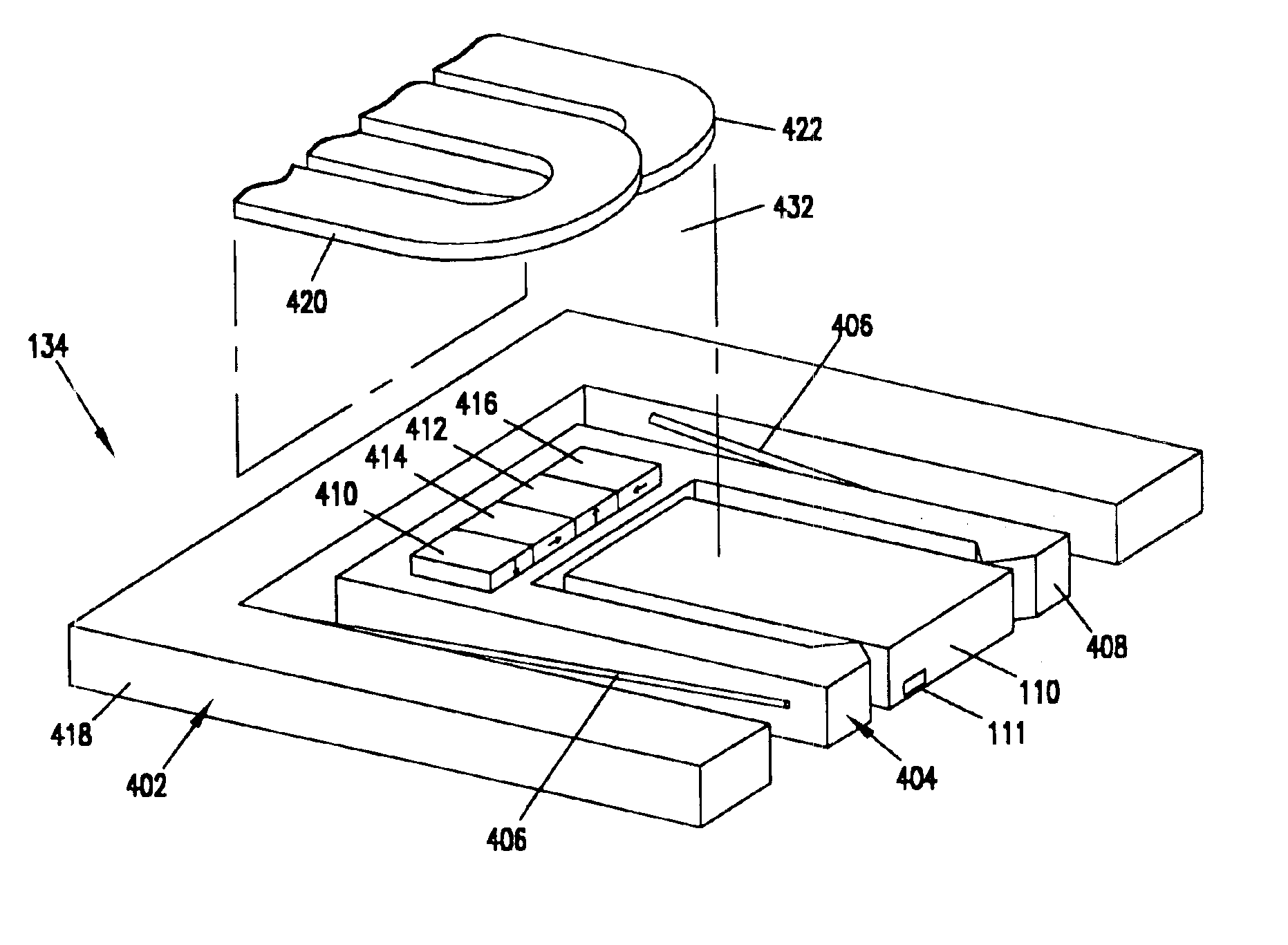
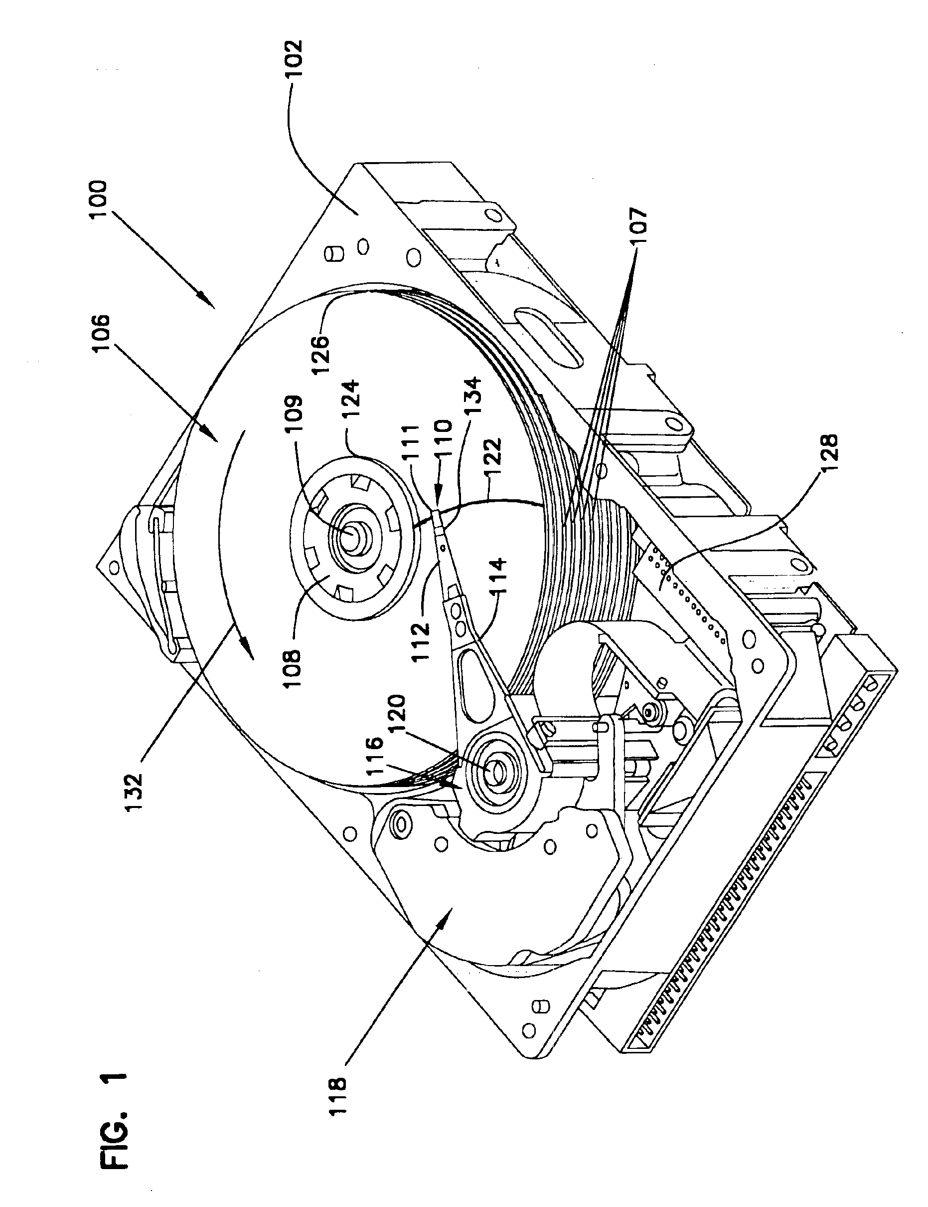
[0017]FIG. 1 is a perspective view of a disc drive 100 in which the present invention is useful. Disc drive 100 includes a housing with a base 102 and a top cover (not shown). Disc drive 100 further includes a disc pack 106, which is mounted on a spindle motor (not shown) by a disc clamp 108 for rotation in the direction of arrow 132. Disc pack 106 includes a plurality of individual discs 107, which are mounted for co-rotation about central axis 109. Each disc surface has an associated slider 110 that is mounted in disc drive 100 for communication with the confronting disc surface. Slider 110 is arranged to fly above the associated disc surface of an individual disc of disc pack 106, and carries a transducing head 111 arranged to write data to, and read data from, concentric tracks on the confronting disc surface. In the example shown in FIG. 1, each slider 110 is supported by a microactuator 134, which in turn is supported by a respective suspension 112. Suspensions 112 are in turn...


PUM


Abstract

A microactuator comprises a stator, a rotor and an operator coupling the rotor to the stator. The operator comprises a four-block magnet array supported by either the stator or rotor, and first and second coils supported by the other of the stator or rotor. Current in one coil alters magnetic flux linkage to move the rotor along a first axis. Current in the other coil alters magnetic flux linkage to move the rotor along a second axis orthogonal to the first axis. The microactuator is applied to the slider of a disc drive to position the head at a selected flying distance adjacent the disc medium, and to position the head relative to a track on the medium.

Description

CROSS-REFERENCE TO RELATED APPLICATION[0001]This application claims priority of U.S. Provisional Application No. 60 / 293,284 filed May 23, 2001 for “Slider Level Microactuator With Integrated Fly Height Control”.FIELD OF THE INVENTION[0002]This invention relates to microactuators for finely positioning a transducing head relative to a desired track in a disc storage device, and particularly to a microactuator that supports the slider and provides fly height control as well as fine positioning.BACKGROUND OF THE INVENTION[0003]As the aerial storage densities of disc drives increases, the distance between adjacent concentric tracks decreases. Decreasing track spacing increases the difficulty of precisely positioning the transducing head over a selected track on the medium. Most disc drives employ a voice coil motor (VCM) that rotates the actuator assembly of the disc drive to position the head relative to the track. However, resonant modes of vibration in the actuator make it increasing...

Claims


Application Information

Patent Timeline
IPC IPC(8): G11B5/55
CPCG11B5/5552
Inventor SUBRAHMANYAN, PRADEEP K.
Owner SEAGATE TECH LLC
Why Eureka
Try Eureka