Fuel container having air supplying device

a fuel container and air supply technology, which is applied in the direction of lighting and heating apparatus, combustion types, applications, etc., can solve the problems of not being able to supply fuel or petroleum or gas to gaseous ovens or stoves that are not suitably changed or converted, and cannot be swiftly or suitably supplied to etc. users of gaseous ovens or stoves may not have a stable supply of fuel or petroleum or gas for cooking purposes, or for water heating purposes

Inactive Publication Date: 2005-05-24
WEN SHIUAN SHIAU
View PDF2 Cites 11 Cited by
  • Summary
  • Abstract
  • Description
  • Claims
  • Application Information

AI Technical Summary

Benefits of technology

[0010]The other objective of the present invention is to provide a fuel container including a heating device to heat and to gasify the fuel or the petroleum or the compressed or liquefied petroleum gases, in order to easily supply air into the container and to other facilities.
[0013]The heating device includes a heater attached to the container body, to heat the petroleum received in the chamber of the container body. The container body includes a bracket, the heating device includes a heat conductive member attached to the container body with the bracket, and the heater is attached to the heat conductive member. A switch attached to the container body, and coupled to the heater, to control the heater and to prevent the petroleum from being over heated.
[0018]The cap includes a hole formed therein, the hole of the cap is openable when the cap is rotated relative to the port of the container body, to prevent the container body from being over-pressurized.

Problems solved by technology

Normally, the compressed or liquefied petroleum gases are in liquid state, and may include a temperature lower than the room temperature, such that the compressed or liquefied petroleum gases may not be suitably changed or converted into a gaseous state, and thus may not be swiftly or suitably supplied to the gaseous ovens or stoves.
Particularly, during the winter season, or when the environment temperature is low, the compressed or liquefied petroleum gases may not be suitably changed or converted into the gaseous state, and such that the users of the gaseous ovens or stoves may not have a stable supplying of the fuel or petroleum or gas for cooking purposes, or for water heating purposes.
Due to the combustible characteristics of the fuel, or gasoline, or petroleum or compressed or liquefied petroleum gases, no heating devices have been developed or provided to heat and to gasify the fuel or the petroleum.

Method used


Image

  • Fuel container having air supplying device
  • Fuel container having air supplying device
  • Fuel container having air supplying device

Examples


Embodiment Construction

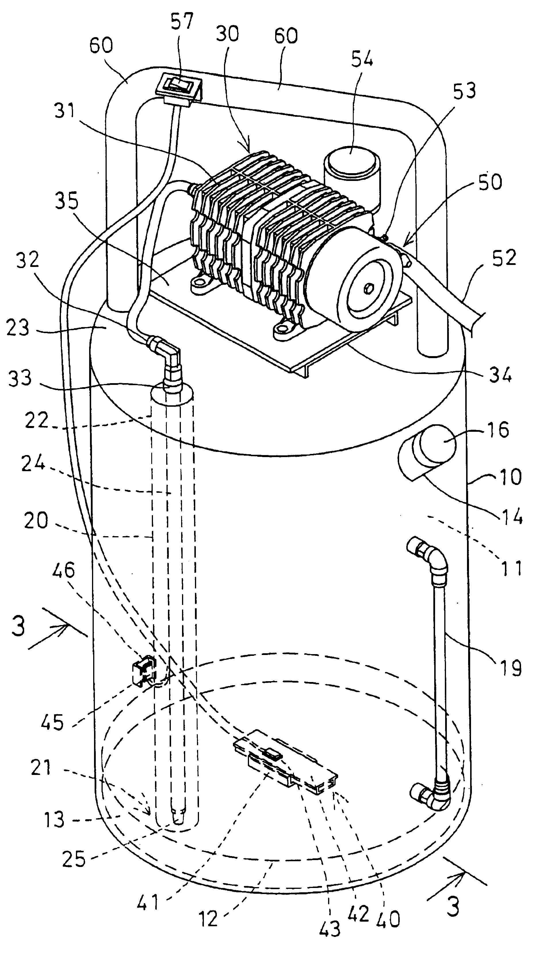
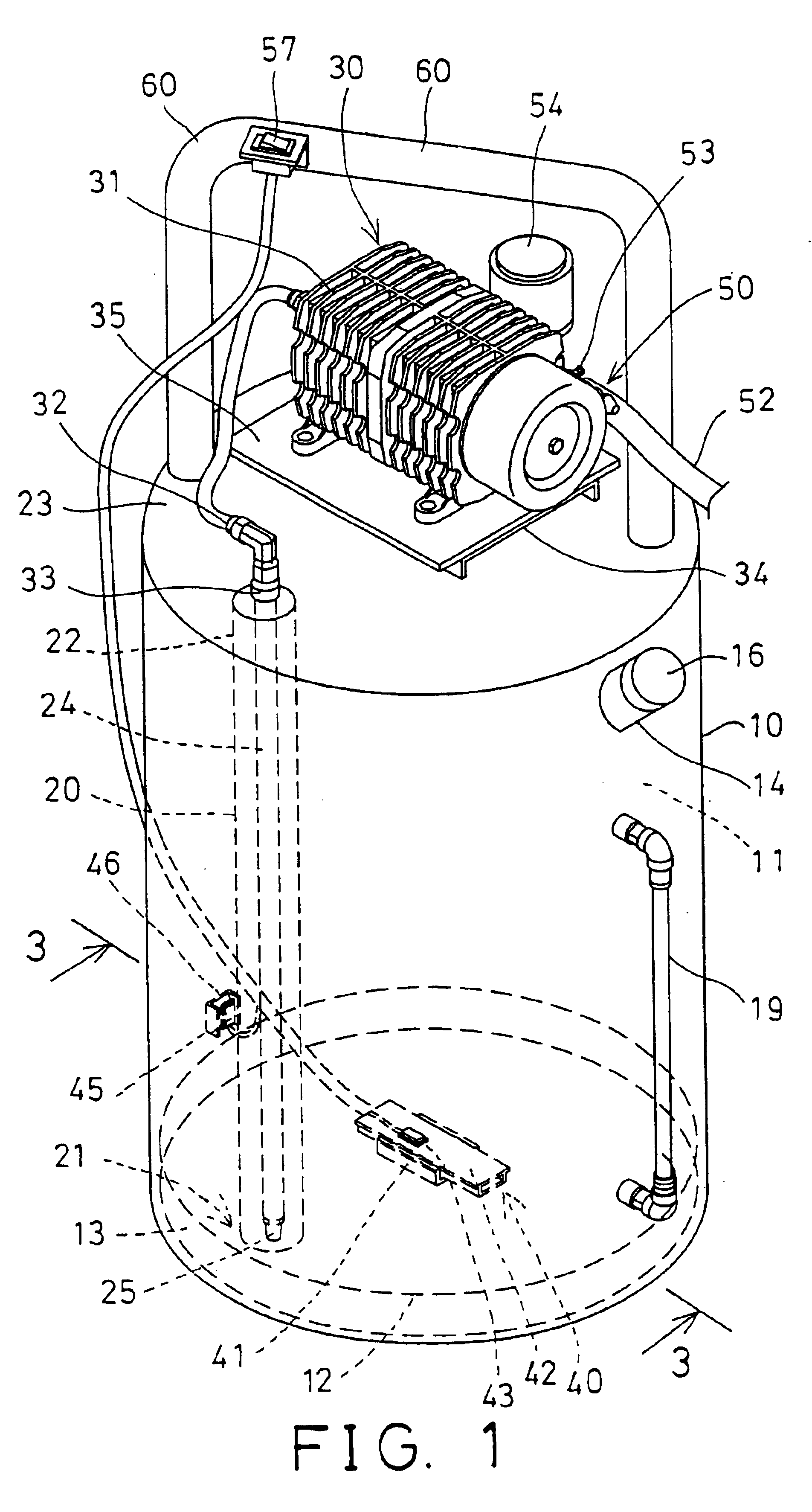
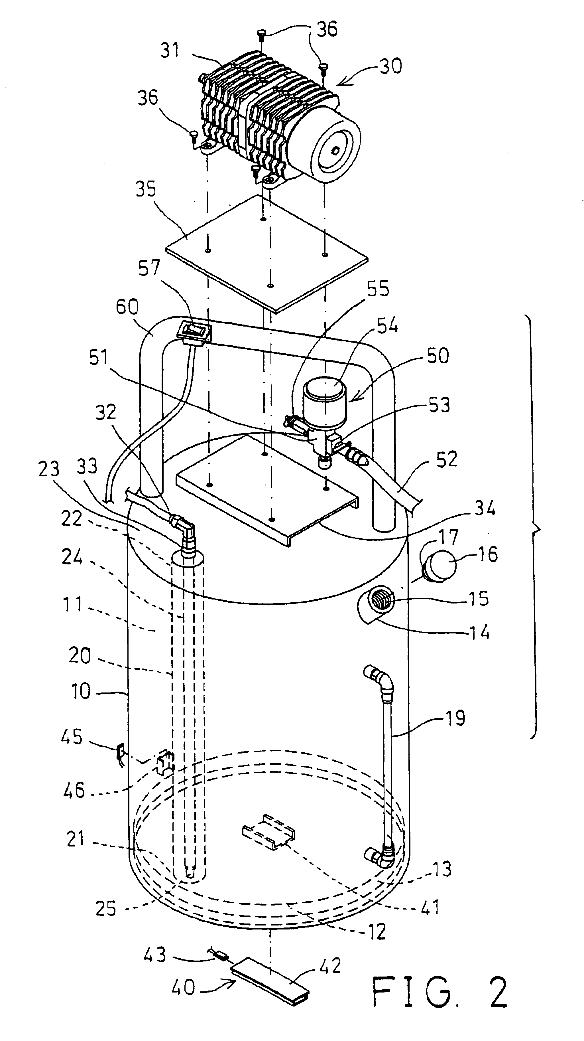
[0030]Referring to the drawings, and initially to FIGS. 1-4, a fuel container in accordance with the present invention comprises a container body 10 including a chamber 11 formed therein and defined by a bottom wall 12 for receiving fuel, gasoline, or petroleum 90, or compressed or liquefied petroleum gases, or other gases, such as ethyne, therein. The petroleum 90 do not completely fill the chamber 11 of the container body 10, and the petroleum 90 may be gradually gasified to gas state or to gasified petroleum 91 and flown upward toward the upper portion of the chamber 11 of the container body 10, for supplying to gas ovens or gas stoves (not shown), or the like.

[0031]The container body 10 includes a recess 13 formed in the bottom thereof and formed or defined below the bottom wall 12, and includes a port 14 having an inner thread 15 formed therein for threading with an outer thread 17 of a cap 16 which may be used to enclose the container body 10, and to stably retain the petroleu...


PUM


Abstract

A fuel container includes a chamber to receive fuel or petroleum or compressed or liquefied petroleum gases, a conduit extended within the chamber of the container to allow the petroleum to flow into and out of the conduit. A pipe is engaged through the container and engaged into the conduit for supplying air into the petroleum received in the conduit and the chamber of the container. An air supplying device includes a pump for pumping and supplying the air into the pipe, and then into the conduit and the chamber of the container, to gasify the petroleum, for allowing the gasified petroleum to be easily flow to gas stoves or ovens.

Description

BACKGROUND OF THE INVENTION[0001]1. Field of the Invention[0002]The present invention relates to a fuel or petroleum container, and more particularly to a fuel container having an air filling or supplying device to supply air into the container, and to gasify the fuel or the petroleum or the compressed or liquefied petroleum gases.[0003]2. Description of the Prior Art[0004]Typical fuel containers comprise a container body for receiving fuel, gasoline, or compressed or liquefied petroleum gases (LPG or LP gas), or other gases, such as ethyne, therein, and a regulator or a control valve attached to the container body, in order to control the outward flowing of the gas to gaseous ovens, stoves, or the like.[0005]Normally, the compressed or liquefied petroleum gases are in liquid state, and may include a temperature lower than the room temperature, such that the compressed or liquefied petroleum gases may not be suitably changed or converted into a gaseous state, and thus may not be swi...

Claims


Application Information

Patent Timeline
Patent Type & Authority Patents(United States)
IPC IPC(8): F23D14/28F23K5/04F23K5/02F23D14/00
CPCF23K5/04F23D14/28
Inventor WEN, SHIUAN SHIAU
Owner WEN SHIUAN SHIAU
Why Eureka
Try Eureka